SEAT BELT WARNING SYSTEM TERMINALS OF ECU
-
CHECK COMBINATION METER ASSEMBLY
-
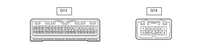
Disconnect the G13 combination meter assembly connector.
-
Measure the resistance and voltage according to the value(s) in the table below.
Tester Connection Wiring Color Terminal Description Condition Specified Condition G13-21 (IG+) - Body ground BE - Body ground IG power supply Power switch on (IG) → off 11 to 14 V → Below 1 V G13-22 (B) - Body ground GR - Body ground Battery power supply Power switch off 11 to 14 V G13-28 (ES) - Body ground BR - Body ground Ground Always Below 1 Ω -
Reconnect the G13 combination meter assembly connector.
-
Measure the voltage according to the value(s) in the table below.
Tester Connection Wiring Color Terminal Description Condition Specified Condition G13-14 (PBKL) - Body ground L - Body ground Front passenger seat belt buckle switch signal Power switch on (IG), front passenger seat occupied, seat belt unfastened → fastened 11 to 14 V → Below 1 V G13-10 (RRSB) - Body ground P - Body ground Rear RH seat belt buckle switch signal Rear RH seat belt unfastened → fastened 11 to 14 V → Below 1 V G13-12 (RLSB) - Body ground G - Body ground Rear LH seat belt buckle switch signal Rear LH seat belt unfastened → fastened 11 to 14 V → Below 1 V G13-26 (CANH) LG - - - G13-27 (CANL) W - - -
-
-
CHECK MAIN BODY ECU (MULTIPLEX NETWORK BODY ECU) AND INSTRUMENT PANEL JUNCTION BLOCK ASSEMBLY

*1 Main Body ECU (Multiplex Network Body ECU) - -
-
Remove the main body ECU (multiplex network body ECU) from the instrument panel junction block assembly.
-
for LHD: Click here
-
for RHD: Click here
-
-
Reconnect the instrument panel junction block assembly connectors.
-
Measure the resistance and voltage according to the value(s) in the table below.
Tester Connection Wiring Color Terminal Description Condition Specified Condition MB-11 (GND1) - Body ground - Ground Always Below 1 Ω MB-30 (ACC) - Body ground - ACC power supply Power switch on (ACC) → off 11 to 14 V → Below 1 V MB-31 (BECU) - Body ground - Battery power supply Power switch off 11 to 14 V MB-32 (IG) - Body ground - IG power supply Power switch on (IG) → off 11 to 14 V → Below 1 V -
Install the main body ECU (multiplex network body ECU) to the instrument panel junction block assembly.
-
for LHD: Click here
-
for RHD: Click here
-
-
Measure the voltage and check for pulses according to the value(s) in the table below.
Tester Connection Wiring Color Terminal Description Condition Specified Condition 4D-25 (LCTY) - Body ground V - Body ground Rear door courtesy light switch LH input Rear door LH closed (OFF) Pulse generation Rear door LH open (ON) Below 1 V 4B-17 (RCTY) - Body ground GR - Body ground Rear door courtesy light switch RH input Rear door RH closed (OFF) Pulse generation Rear door RH open (ON) Below 1 V
-
-
CHECK AIRBAG SENSOR ASSEMBLY
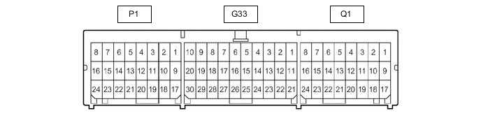
Terminal No. Terminal Symbol Destination P1-10 (for LHD) LBE+ Front seat inner belt assembly LH P1-18 (for LHD) LBE- Front seat inner belt assembly LH Q1-15 (for RHD) RBE+ Front seat inner belt assembly RH Q1-23 (for RHD) RBE- Front seat inner belt assembly RH