SEAT HEATER SYSTEM Seat Heater for Rear Left Seat does not Operate
DESCRIPTION
When the rear seat heater switch LH is operated, the rear seat heater LH operates.
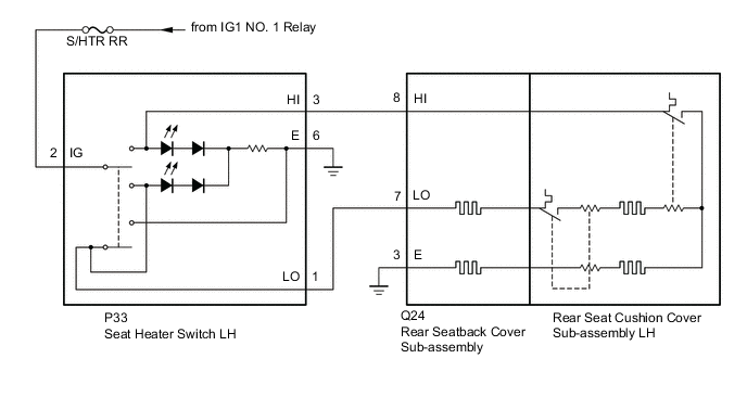
WIRING DIAGRAM
CAUTION / NOTICE / HINT
Note
Inspect the fuses and relays for circuits related to this system before performing the following inspection procedure.
PROCEDURE
-
INSPECT REAR SEAT HEATER SWITCH LH
-
Remove the rear seat heater switch LH.
-
Inspect the rear seat heater switch LH.
Result Proceed to OK NG
NG 
REPLACE REAR SEAT HEATER SWITCH LH Click here
OK 
-
-
CHECK HARNESS AND CONNECTOR (REAR SEAT HEATER SWITCH LH - POWER SOURCE AND BODY GROUND)
-
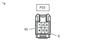
*a Front view of wire harness connector
(to Rear Seat Heater Switch LH)
Disconnect the rear seat heater switch LH connector.
-
Measure the voltage according to the value(s) in the table below.
Standard Voltage Tester Connection Switch Condition Specified Condition P33-2 (IG) - Body ground Power switch on (IG) 11 to 14 V -
Measure the resistance according to the value(s) in the table below.
Standard Resistance Tester Connection Condition Specified Condition P33-6 (E) - Body ground Always Below 1 Ω Result Proceed to OK NG
NG
REPAIR OR REPLACE HARNESS OR CONNECTOR
OK
-
-
CHECK HARNESS AND CONNECTOR (REAR SEAT HEATER SWITCH LH - REAR SEATBACK COVER SUB-ASSEMBLY)
-
Disconnect the P33 rear seat heater switch LH connector.
-
Disconnect the Q24 rear seatback cover sub-assembly connector.
-
Measure the resistance according to the value(s) in the table below.
Standard Resistance Tester Connection Condition Specified Condition P33-3 (HI) - Q24-8 (HI) Always Below 1 Ω P33-3 (HI) - Body ground Always 10 KΩ or higher Q24-8 (HI) - Body ground Always 10 KΩ or higher P33-1 (LO) - Q24-7 (LO) Always Below 1 Ω P33-1 (LO) - Body ground Always 10 KΩ or higher Q24-7 (LO) - Body ground Always 10 KΩ or higher Result Proceed to OK NG
NG
REPAIR OR REPLACE HARNESS OR CONNECTOR
OK
-
-
CHECK HARNESS AND CONNECTOR (REAR SEATBACK COVER SUB-ASSEMBLY - BODY GROUND)
-
Disconnect the Q24 rear seatback cover sub-assembly connector.
-
Measure the resistance according to the value(s) in the table below.
Standard Resistance Tester Connection Condition Specified Condition Q24-3 (E) - Body ground Always Below 1 Ω Result Proceed to OK NG
NG
REPAIR OR REPLACE HARNESS OR CONNECTOR
OK
-
-
INSPECT REAR SEATBACK COVER SUB-ASSEMBLY
-
Remove the rear seatback cover sub-assembly.
-
Inspect the rear seatback cover sub-assembly.
Result Proceed to OK NG
OK
END (REAR SEAT CUSHION COVER SUB-ASSEMBLY LH WAS DEFECTIVE)
NG
REPLACE REAR SEATBACK COVER SUB-ASSEMBLY Click here
-