SEAT HEATER SYSTEM Seat Heater for Front Left Seat does not Operate
DESCRIPTION
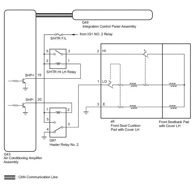
The integration control and panel assembly (seat heater switch (driver seat)) sends operation signals to the air conditioner amplifier assembly via CAN communication. The air conditioner amplifier assembly operates the seat heater (driver seat) based on the received signals.
WIRING DIAGRAM
CAUTION / NOTICE / HINT
Note
-
Inspect the fuses for circuits related to this system before performing the following procedure.
-
When the auxiliary battery is disconnected, or the servo motor or air conditioning amplifier assembly is replaced, be sure to perform servo motor initialization.
PROCEDURE
-
CHECK HEATER AND AIR CONDITIONER OPERATION
-
Check air conditioning system operation.
OK Air conditioning system is normal. Result Proceed to OK NG
NG 
GO TO HEATER AND AIR CONDITIONER SYSTEM Click here
OK 
-
-
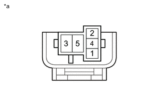
INSPECT S/HTR HI LH RELAY AND HEATER RELAY NO. 2
-
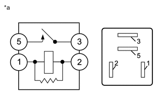
*a Component without harness connected
(S/HTR HI LH Relay)
S/HTR HI LH relay
-
Remove the S/HTR HI LH relay from the No. 3 relay box.
-
Measure the resistance according to the value(s) in the table below.
Standard Resistance Tester Connection Condition Specified Condition 3-5 Auxiliary battery voltage not applied to terminals 1 and 2 10 KΩ or higher Auxiliary battery voltage applied to terminals 1 and 2 Below 1 Ω
-
-
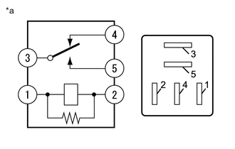
*a Component without harness connected
(Heater Relay No. 2)
Heater relay No. 2
-
Remove the heater relay No. 2 from the relay holder.
-
Measure the resistance according to the value(s) in the table below.
Standard Resistance Tester Connection Condition Specified Condition G97-3 - G97-4 Auxiliary battery voltage not applied to terminals 1 and 2 Below 1 Ω Auxiliary battery voltage applied to terminals 1 and 2 10 KΩ or higher G97-3 - G97-5 Auxiliary battery voltage not applied to terminals 1 and 2 10 KΩ or higher Auxiliary battery voltage applied to terminals 1 and 2 Below 1 Ω G97-4 - G97-5 Always 10 KΩ or higher
Result Proceed to OK NG -
NG
REPLACE S/HTR HI LH RELAY OR HEATER RELAY NO. 2
OK
-
-
CHECK HARNESS AND CONNECTOR (S/HTR HI LH RELAY AND HEATER RELAY NO. 2 - POWER SOURCE CIRCUIT)
-
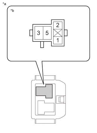
*a No. 3 Relay Box *b S/HTR HI LH Relay Holder S/HTR HI LH relay
-
Remove the S/HTR HI LH relay from the No. 3 relay box.
-
Measure the voltage according to the value(s) in the table below.
Standard Voltage Tester Connection Switch Condition Specified Condition S/HTR HI LH relay holder (2) - Body ground Power switch on (IG) 11 to 14 V S/HTR HI LH relay holder (2) - Body ground Power switch off Below 1 V S/HTR HI LH relay holder (5) - Body ground Power switch on (IG) 11 to 14 V S/HTR HI LH relay holder (5) - Body ground Power switch off Below 1 V
-
-
*a Relay Holder Heater relay No. 2
-
Remove the heater relay No. 2 from the relay holder.
-
Measure the voltage according to the value(s) in the table below.
Standard Voltage Tester Connection Switch Condition Specified Condition G97-1 - Body ground Power switch on (IG) 11 to 14 V G97-1 - Body ground Power switch off Below 1 V G97-5 - Body ground Power switch on (IG) 11 to 14 V G97-5 - Body ground Power switch off Below 1 V -
Measure the resistance according to the value(s) in the table below.
Standard Resistance Tester Connection Condition Specified Condition G97-4 - Body ground Always Below 1 Ω
Result Proceed to OK NG -
NG
REPAIR OR REPLACE HARNESS OR CONNECTOR
OK
-
-
CHECK HARNESS AND CONNECTOR (S/HTR HI LH RELAY AND HEATER RELAY NO. 2 - AIR CONDITIONING AMPLIFIER ASSEMBLY)
-
S/HTR HI LH relay
-
Disconnect the G43 air conditioning amplifier assembly connector.
-
Measure the resistance according to the value(s) in the table below.
Standard Resistance Tester Connection Condition Specified Condition S/HTR HI LH relay holder (1) - G43-19 (SHP+) Always Below 1 Ω G43-19 (SHP+) - Body ground Always 10 KΩ or higher S/HTR HI LH relay holder (1) - Bodyground Always 10 KΩ or higher
-
-
Heater relay No. 2
-
Disconnect the G43 air conditioning amplifier assembly connector.
-
Measure the resistance according to the value(s) in the table below.
Standard Resistance Tester Connection Condition Specified Condition Heater relay No. 2 holder (2) - G43-20 (SHP-) Always Below 1 Ω G43-20 (SHP-) - Body ground Always 10 KΩ or higher Heater relay No. 2 holder (2) - Body ground Always 10 KΩ or higher
Result Proceed to OK NG -
NG
REPAIR OR REPLACE HARNESS OR CONNECTOR
OK
-
-
CHECK HARNESS AND CONNECTOR (S/HTR HI LH RELAY AND HEATER RELAY NO. 2 - FRONT SEAT CUSHION PAD WITH COVER LH)
-
S/HTR HI LH relay
-
Disconnect the a6 front seat cushion pad with cover LH connector.
-
Measure the resistance according to the value(s) in the table below.
Standard Resistance Tester Connection Condition Specified Condition S/HTR HI LH relay holder (3) - a6-2 Always Below 1 Ω S/HTR HI LH relay holder (3) - Body ground Always 10 KΩ or higher a6-2 - Body ground Always 10 KΩ or higher
-
-
Heater relay No. 2
-
Disconnect the a6 front seat cushion pad with cover LH connector.
-
Measure the resistance according to the value(s) in the table below.
Standard Resistance Tester Connection Condition Specified Condition Heater relay No. 2 holder (3) - a6-1 Always Below 1 Ω Heater relay No. 2 holder (3) - Body ground Always 10 KΩ or higher a6-1-Body ground Always 10 KΩ or higher
Result Proceed to OK NG -
NG
REPAIR OR REPLACE HARNESS OR CONNECTOR
OK
-
-
CHECK HARNESS AND CONNECTOR (FRONT SEAT CUSHION PAD WITH COVER LH - BODY GROUND)
-
Measure the resistance according to the value(s) in the table below.
Standard Resistance Tester Connection Condition Specified Condition a6-3 - Body ground Always Below 1 Ω Result Proceed to OK NG
NG
REPAIR OR REPLACE HARNESS OR CONNECTOR
OK
-
-
INSPECT FRONT SEAT CUSHION PAD WITH COVER LH
-
Remove the front seat cushion pad with cover LH.
-
Inspect the front seat cushion pad with cover LH.
Result Proceed to OK NG
NG
REPLACE FRONT SEAT CUSHION PAD WITH COVER LH Click here
OK
-
-
INSPECT FRONT SEATBACK PAD WITH COVER LH
-
Remove the front seatback pad with cover LH.
Click here
-
Inspect the front seatback pad with cover LH.
Click here
Result Proceed to OK NG
NG
REPLACE FRONT SEATBACK PAD WITH COVER LH Click here
OK
-
-
CHECK SEAT HEATER OPERATION
-
Temporarily replace the integration control panel assembly with a new or known good one.
-
Check the seat heater.
OK The seat heater operates normally. Result Proceed to OK NG
OK
END (INTEGRATION CONTROL PANEL ASSEMBLY WAS DEFECTIVE)
NG
REPLACE AIR CONDITIONING AMPLIFIER ASSEMBLY Click here
-