SEAT HEATER SYSTEM TERMINALS OF ECU
-
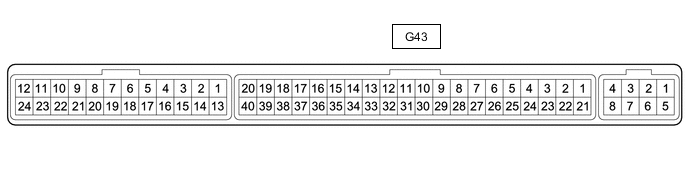
CHECK AIR CONDITIONING AMPLIFIER ASSEMBLY
-
Disconnect the G43 air conditioning amplifier assembly connector.
-
Measure the voltage and resistance according to the value(s) in the table below.
Tester Connection Wiring Color Terminal Description Condition Specified Condition G43-1 (IG+) - Body ground B - Body ground IG power supply Power switch on (IG) 11 to 14 V Power switch off Below 1 V G43-14 (GND) - Body ground W-B - Body ground Ground Always Below 1 Ω G43-21 (B) - Body ground GR - Body ground Auxiliary battery power supply Power switch off 11 to 14 V -
Reconnect the G43 air conditioning amplifier assembly connector.
-
Measure the voltage according to the value(s) in the table below.
-
Check for pulse generation according to the value(s) in the table below.
Tester Connection Wiring Color Terminal Description Condition Specified Condition G43-11 (CANH) - Body ground LG - Body ground Seat heater switch signal Power switch on (IG) Pulse generation G43-12 (CANL) - Body ground W - Body ground Seat heater switch signal Power switch on (IG) Pulse generation G43-17 (SHD+) - G43-14 (GND) LG - W-B Seat heater (for Driver Side) input signal
-
Power switch on (IG)
-
Seat heater switch (for Front Driver Side) from OFF to HI
11 to 14 V Power switch off Below 1 V G43-18 (SHD-) - G43-14 (GND) LG - W-B Seat heater (for Driver Side) input signal
-
Power switch on (IG)
-
Seat heater switch (for Front Driver Side) from OFF to LO
11 to 14 V Power switch off Below 1 V G43-19 (SHP+) - G43-14 (GND) SB - W-B Seat heater (for Front Passenger Side) drive signal
-
Power switch on (IG)
-
Seat heater switch (for Front Passenger Side) from OFF to HI
11 to 14 V Power switch off Below 1 V G43-20 (SHP-) - G43-14 (GND) LG - W-B Seat heater (for Front Passenger Side) drive signal
-
Power switch on (IG)
-
Seat heater switch (for Front Passenger Side) from OFF to LO
11 to 14 V Power switch off Below 1 V -
-
-
CHECK INTEGRATION CONTROL PANEL ASSEMBLY

-
Disconnect the G49 integration control panel assembly connector.
-
Measure the voltage and resistance according to the value(s) in the table below.
Tester Connection Wiring Color Terminal Description Condition Specified Condition G49-16 (GND) - Body ground W-B - Body ground Ground Always Below 1 Ω G49-9 (IG+) - G49-16 (GND) P - W-B IG power supply Power switch on (IG) 11 to 14 V Power switch off Below 1 V -
Reconnect the G49 integration control panel assembly connector.
-
Check for pulse generation according to the value(s) in the table below.
Tester Connection Wiring Color Terminal Description Condition Specified Condition G49-4 (CANH) - G49-16 (GND) BR - W-B Seat heater switch signal Power switch on (IG) Pulse generation G49-5 (CANL) - G49-16 (GND) W - W-B Seat heater switch signal Power switch on (IG) Pulse generation
-