FRONT POWER SEAT CONTROL SYSTEM(w/ Memory), Diagnostic DTC:B2658
| DTC Code | DTC Name |
|---|---|
| B2658 | Short in Sensor with Motor Power Supply Circuit |
DESCRIPTION
This DTC is stored when a power seat motor operates (a position control sensor is being supplied with power) and the power supply voltage does not rise to the specified value.
| DTC No. | Detection Item | DTC Detection Condition | Trouble Area |
|---|---|---|---|
| B2658 | Short in Sensor with Motor Power Supply Circuit | Problem with the voltage supplied to the position control sensor. |
|
WIRING DIAGRAM
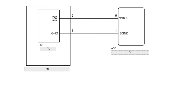
| *a | O/P |
| *b | Slide Motor |
| *c | Front Power Seat Switch LH |
| *d | Front Seat Adjuster Assembly LH |
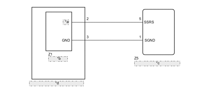
| *a | O/P |
| *b | Slide Motor |
| *c | Front Power Seat Switch RH |
| *d | Front Seat Adjuster Assembly RH |
PROCEDURE
-
CLEAR DTC
-
Clear the DTCs.
Body Electrical > Driver Seat > Clear DTCsResult Proceed to NEXT
NEXT 
-
-
CHECK FOR DTC
-
Check for DTCs.
Body Electrical > Driver Seat > Trouble CodesOK DTC B2658 is not output. Result Result Proceed to OK A NG (for LHD) B NG (for RHD) C
A 
USE SIMULATION METHOD TO CHECK Click here
C 
CHECK HARNESS AND CONNECTOR (FRONT POWER SEAT SWITCH RH - SLIDE MOTOR (FRONT SEAT ADJUSTER ASSEMBLY RH)) Click here
B
-
-
CHECK HARNESS AND CONNECTOR (FRONT POWER SEAT SWITCH LH - SLIDE MOTOR (FRONT SEAT ADJUSTER ASSEMBLY LH))
-
Disconnect the a10 front power seat switch LH connector.
-
Disconnect the a8 slide motor (front seat adjuster assembly LH) connector.
-
Measure the resistance according to the value(s) in the table below.
Standard Resistance Tester Connection Condition Specified Condition a10-5 (SSRS) - a8-2 (O/P) Always Below 1 Ω a10-5 (SSRS) - Body ground Always 10 kΩ or higher a8-2 (O/P) - Body ground Always 10 kΩ or higher a10-1 (SGND) - a8-3 (GND) Always Below 1 Ω a10-1 (SGND) - Body ground Always 10 kΩ or higher a8-3 (GND) - Body ground Always 10 kΩ or higher Result Proceed to OK NG
NG
REPAIR OR REPLACE HARNESS AND CONNECTOR
OK
-
-
CHECK FRONT POWER SEAT SWITCH LH (SLIDE MOTOR CIRCUIT)
-
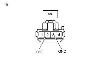
*a Front view of wire harness connector
(to Slide Motor (Front Seat Adjuster Assembly LH))
Reconnect the slide motor (front seat adjuster assembly LH) connector.
-
Measure the voltage according to the value(s) in the table below.
Standard Voltage Tester Connection Switch Condition Specified Condition a8-2 (O/P) - a8-3 (GND) Sliding switch on 4.8 to 5.1 V Result Proceed to OK NG
OK
REPLACE FRONT SEAT ADJUSTER ASSEMBLY LH Click here
NG
REPLACE FRONT POWER SEAT SWITCH LH Click here
-
-
CHECK HARNESS AND CONNECTOR (FRONT POWER SEAT SWITCH RH - SLIDE MOTOR (FRONT SEAT ADJUSTER ASSEMBLY RH))
-
Disconnect the Z5 front power seat switch RH connector.
-
Disconnect the Z1 slide motor (front seat adjuster assembly RH) connector.
-
Measure the resistance according to the value(s) in the table below.
Standard Resistance Tester Connection Condition Specified Condition Z5-5 (SSRS) - Z1-2 (O/P) Always Below 1 Ω Z5-5 (SSRS) - Body ground Always 10 kΩ or higher Z1-2 (O/P) - Body ground Always 10 kΩ or higher Z5-1 (SGND) - Z1-3 (GND) Always Below 1 Ω Z5-1 (SGND) - Body ground Always 10 kΩ or higher Z1-3 (GND) - Body ground Always 10 kΩ or higher Result Proceed to OK NG
NG
REPAIR OR REPLACE HARNESS AND CONNECTOR
OK
-
-
CHECK FRONT POWER SEAT SWITCH RH (SLIDE MOTOR CIRCUIT)
-
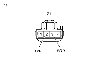
*a Front view of wire harness connector
(to Slide Motor (Front Seat Adjuster Assembly RH))
Reconnect the slide motor (front seat adjuster assembly RH) connector.
-
Measure the voltage according to the value(s) in the table below.
Standard Voltage Tester Connection Switch Condition Specified Condition Z1-2 (O/P) - Z1-3 (GND) Sliding switch on 4.8 to 5.1 V Result Proceed to OK NG
OK
REPLACE FRONT SEAT ADJUSTER ASSEMBLY RH Click here
NG
REPLACE FRONT POWER SEAT SWITCH RH Click here
-