PRE-CRASH SAFETY SYSTEM Pre-crash Safety System Switch Circuit
DESCRIPTION
Each time the pre-crash system cancel switch assembly is pressed, the multi-information display sensitivity setting display changes to switch the sensitivity of the pre-crash safety system between 3 levels. Also, when the switch is pressed and held, the pre-crash safety system cancels.
WIRING DIAGRAM
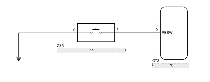
| *a | Pre-crash System Cancel Switch Assembly |
| *b | Driving Support ECU Assembly |
CAUTION / NOTICE / HINT
Note
When replacing the driving support ECU assembly, always replace it with a new one. If a driving support ECU assembly which was installed to another vehicle is used, the information stored in the driving support ECU assembly will not match the information from the vehicle. As a result, a DTC may be stored.
PROCEDURE
-
READ VALUE USING GTS (PCS OFF SWITCH)
-
Connect the GTS to the DLC3.
-
Turn the power switch on (IG).
-
Turn the GTS on.
-
Enter the following menus: Body Electrical / Pre-Crash 2 / Data List.
-
Read the Data List according to the display on the GTS.
Body Electrical > Pre-Crash 2 > Data ListTester Display Measurement Item Range Normal Condition Diagnostic Note PCS OFF Switch Pre-crash system cancel switch assembly status ON or OFF ON: Pre-crash safety system function disabled due to switch operation
OFF: Pre-crash safety system function enabled due to switch operation
-
Body Electrical > Pre-Crash 2 > Data ListTester Display PCS OFF Switch OK When the pre-crash system cancel switch assembly is operated, the display changes as shown above. Result Proceed to OK NG
OK 
PROCEED TO NEXT SUSPECTED AREA SHOWN IN PROBLEM SYMPTOMS TABLE Click here
NG 
-
-
INSPECT PRE-CRASH SYSTEM CANCEL SWITCH ASSEMBLY
-
Remove the pre-crash system cancel switch assembly.
-
Inspect the pre-crash system cancel switch assembly.
Result Proceed to OK NG
NG
REPLACE PRE-CRASH SYSTEM CANCEL SWITCH ASSEMBLY Click here
OK
-
-
CHECK HARNESS AND CONNECTOR (PRE-CRASH SYSTEM CANCEL SWITCH ASSEMBLY - DRIVING SUPPORT ECU ASSEMBLY AND BODY GROUND)
-
Disconnect the G75 pre-crash system cancel switch assembly connector.
-
Disconnect the G72 driving support ECU assembly connector.
-
Measure the resistance according to the value(s) in the table below.
Standard Resistance Tester Connection Condition Specified Condition G75-1 - G72-5 (PBSW) Always Below 1 Ω G75-1 or G72-5 (PBSW) - Body ground Always 10 kΩ or higher G75-2 - Body ground Always Below 1 Ω Result Result Proceed to OK (for LHD) A OK (for RHD) B NG C
A
REPLACE DRIVING SUPPORT ECU ASSEMBLY Click here
B
REPLACE DRIVING SUPPORT ECU ASSEMBLY Click here
C
REPAIR OR REPLACE HARNESS OR CONNECTOR
-