PRE-CRASH SAFETY SYSTEM, Diagnostic DTC:C1A4A
| DTC Code | DTC Name |
|---|---|
| C1A4A | Skid Control Buzzer Circuit |
DESCRIPTION
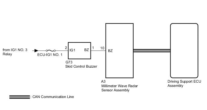
Based on pre-crash safety control, the driving support ECU assembly provides warnings to the driver. The driving support ECU assembly does this by sending a request signal to the millimeter wave radar sensor assembly to sound the skid control buzzer.
When the millimeter wave radar sensor assembly detects a malfunction in the skid control buzzer circuit, a malfunction signal is sent to the driving support ECU assembly, and this DTC is stored.
| DTC No. | Detection Item | DTC Detection Condition | Trouble Area |
|---|---|---|---|
| C1A4A | Skid Control Buzzer Circuit | While the power switch is on (IG), a skid control buzzer circuit malfunction signal is received from the millimeter wave radar sensor assembly for 3 seconds or more. |
|
WIRING DIAGRAM
CAUTION / NOTICE / HINT
Note
-
Inspect the fuses for circuits related to this system before performing the following procedure.
-
When the millimeter wave radar sensor assembly is replaced with a new one, adjustment of the radar sensor beam axis must be performed.
-
When replacing the driving support ECU assembly, always replace it with a new one. If a driving support ECU assembly which was installed to another vehicle is used, the information stored in the driving support ECU assembly will not match the information from the vehicle. As a result, a DTC may be stored.
PROCEDURE
-
CHECK FOR DTCs (PRE-CRASH 2)
-
Clear the DTCs.
Body Electrical > Pre-Crash 2 > Clear DTCs -
Make sure that the DTC detection conditions are met.
Tech Tips
If the detection conditions are not met, the system cannot detect the malfunction.
-
Check for DTCs.
Body Electrical > Pre-Crash 2 > Trouble CodesResult Result Proceed to DTC C1A4A, U1002, U0235 and U1104 are not output A DTC C1A4A is output B DTC C1A4A and U0235 are output C DTC C1A4A and U1002 are output D DTC C1A4A and U1104 are output E
A 
USE SIMULATION METHOD TO CHECK Click here
C
GO TO DTC U0235 Click here
D
GO TO DTC U1002 Click here
E
GO TO DTC U1104 Click here
B 
-
-
PERFORM ACTIVE TEST USING GTS (SKID CONTROL BUZZER)
-
Connect the GTS to the DLC3.
-
Turn the power switch on (IG).
-
Turn the GTS on.
-
Enter the following menus: Body Electrical / Pre-Crash 2 / Active Test.
-
Perform "Active Test" according to the display on GTS.
Body Electrical > Pre-Crash 2 > Active TestTester Display Measurement Item Control Range Diagnostic Note PCS Crash Alarm Buzzer Skid control buzzer ON or OFF Buzzer can be heard PCS Approach Alarm Buzzer Skid control buzzer ON or OFF Buzzer can be heard
Body Electrical > Pre-Crash 2 > Active TestTester Display PCS Crash Alarm Buzzer
Body Electrical > Pre-Crash 2 > Active TestTester Display PCS Approach Alarm Buzzer OK Skid control buzzer sounds. Result Result Proceed to OK (for LHD) A OK (for RHD) B NG C
A
REPLACE DRIVING SUPPORT ECU ASSEMBLY Click here
B
REPLACE DRIVING SUPPORT ECU ASSEMBLY Click here
C
-
-
INSPECT SKID CONTROL BUZZER
-
Remove the skid control buzzer.
-
Inspect the skid control buzzer.
Result Proceed to OK NG
NG
REPLACE SKID CONTROL BUZZER Click here
OK
-
-
CHECK HARNESS AND CONNECTOR (SKID CONTROL BUZZER - BATTERY)
-
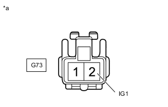
*a Front view of wire harness connector
(to Skid Control Buzzer)
Disconnect the skid control buzzer connector.
-
Measure the voltage according to the value(s) in the table below.
Standard Voltage Tester Connection Switch Condition Specified Condition G73-2 (IG1) - Body ground Power switch on (IG) 11 to 14 V G73-2 (IG1) - Body ground Power switch off Below 1 V Result Proceed to OK NG
NG
REPAIR OR REPLACE HARNESS OR CONNECTOR
OK
-
-
CHECK HARNESS AND CONNECTOR (SKID CONTROL BUZZER - MILLIMETER WAVE RADAR SENSOR ASSEMBLY)
-
Disconnect the G73 skid control buzzer connector.
-
Disconnect the A3 millimeter wave radar sensor assembly connector.
-
Measure the resistance according to the value(s) in the table below.
Standard Resistance Tester Connection Condition Specified Condition G73-1 (BZ) - A3-10 (BZ) Always Below 1 Ω G73-1 (BZ) - Body ground Always 10 kΩ or higher Result Proceed to OK NG
NG
REPAIR OR REPLACE HARNESS OR CONNECTOR
OK
-
-
REPLACE MILLIMETER WAVE RADAR SENSOR ASSEMBLY
-
Replace the millimeter wave radar sensor assembly with a new one.
-
Perform millimeter wave radar sensor assembly adjustment.
Result Proceed to NEXT
NEXT
-
-
CHECK FOR DTCs (PRE-CRASH 2)
-
Clear the DTCs.
Body Electrical > Pre-Crash 2 > Clear DTCs -
Make sure that the DTC detection conditions are met.
Tech Tips
If the detection conditions are not met, the system cannot detect the malfunction.
-
Check for DTCs.
Body Electrical > Pre-Crash 2 > Trouble CodesResult Result Proceed to DTC C1A4A is not output A DTC C1A4A is output (for LHD) B DTC C1A4A is output (for RHD) C
A
END (MILLIMETER WAVE RADAR SENSOR ASSEMBLY WAS DEFECTIVE)
B
REPLACE DRIVING SUPPORT ECU ASSEMBLY Click here
C
REPLACE DRIVING SUPPORT ECU ASSEMBLY Click here
-