PRE-CRASH SAFETY SYSTEM TERMINALS OF ECU
-
CHECK DRIVING SUPPORT ECU ASSEMBLY

-
Disconnect the G72 driving support ECU assembly connector.
Note
If a load of more than 10 kg (22 lb.) is placed on the connector, it may break. Do not place more load than is necessary on the connector.
-
Measure the voltage and resistance according to the value(s) in the table below.
Terminal No. (Symbol) Wiring Color Terminal Description Condition Specified Condition G72-5 (PBSW) - Body ground B - Body ground Pre-crash system cancel switch assembly signal Pre-crash system cancel switch assembly on Below 1 Ω Pre-crash system cancel switch assembly off 10 kΩ or higher G72-25 (GND) - Body ground W-B - Body ground Ground Always Below 1 Ω G72-30 (B) - Body ground G - Body ground Power source Power switch on (IG) 11 to 14 V Power switch off Below 1 V Tech Tips
If the result is not as specified, there may be a malfunction on the wire harness side.
-
Reconnect the G72 driving support ECU assembly connector.
-
Check for pulses according to the value(s) in the table below.
Terminal No. (Symbol) Wiring Color Terminal Description Condition Specified Condition G72-17 (CA2L) - G72-25 (GND) W - W-B CAN communication signal Power switch on (IG) Pulse generation
(See waveform 1)
G72-18 (CA1N) - G72-25 (GND) W - W-B CAN communication signal Power switch on (IG) Pulse generation
(See waveform 2)
G72-39 (CA2H) - G72-25 (GND) BR - W-B CAN communication signal Power switch on (IG) Pulse generation
(See waveform 3)
G72-40 (CA1P) - G72-25 (GND) B - W-B CAN communication signal Power switch on (IG) Pulse generation
(See waveform 4)
-
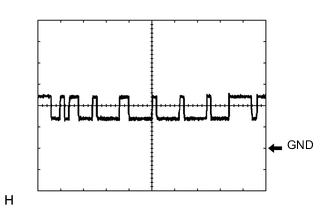
Waveform 1
-
CAN communication signal
Item Content Tester Connection G72-17 (CA2L) - G72-25 (GND) Tool Setting 1 V/DIV., 10 μsec./DIV. Condition Power switch on (IG) Tech Tips
The waveform varies depending on the CAN communication signal.
-
-
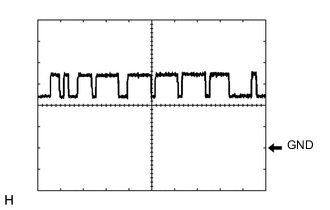
Waveform 2
-
CAN communication signal
Item Content Tester Connection G72-18 (CA1N) - G72-25 (GND) Tool Setting 1 V/DIV., 10 μsec./DIV. Condition Power switch on (IG) Tech Tips
The waveform varies depending on the CAN communication signal.
-
-
Waveform 3
-
CAN communication signal
Item Content Tester Connection G72-39 (CA2H) - G72-25 (GND) Tool Setting 1 V/DIV., 10 μsec./DIV. Condition Power switch on (IG) Tech Tips
The waveform varies depending on the CAN communication signal.
-
-
Waveform 4
-
CAN communication signal
Item Content Tester Connection G72-40 (CA1P) - G72-25 (GND) Tool Setting 1 V/DIV., 10 μsec./DIV. Condition Power switch on (IG) Tech Tips
The waveform varies depending on the CAN communication signal.
-
-