PRE-CRASH SAFETY SYSTEM HOW TO PROCEED WITH TROUBLESHOOTING
| DTC Code | DTC Name |
|---|---|
| HOW TO PROCEED WITH TROUBLESHOOTING |
CAUTION / NOTICE / HINT
Tech Tips
-
Use the following procedure to troubleshoot the pre-crash safety system.
-
*: Use the GTS.
PROCEDURE
-
VEHICLE BROUGHT TO WORKSHOP
Result Proceed to NEXT
NEXT 
-
CUSTOMER PROBLEM ANALYSIS AND SYMPTOM CHECK
Pre-crash Safety System Customer Problem Analysis Vehicle Brought to Workshop Year Month Day Name Registration No. First Registered Year Vehicle Model Frame No. Customer Concerns Problem symptoms first occurred Year Month Day Approx. Time Frequency of problem symptoms Continuously / Occasionally (times per day, times per month) / Only Once Weather Sunny / Cloudy / Rain / Snow / Other ( ) Temperature About °C ( °F) Place Prefecture Conditions Urban area / Suburbs / Highway / Other ( ) Conditions Direction of travel Straight / Right turn / Left turn / Right curve / Left curve Driving lane Number of lanes on one side (lanes) / ( ) lane(s) from left Lane width m Details of driving conditions at time of occurrence (driving lane, driving route, position and type of surrounding vehicles, etc.) *Please include detailed diagram on Additional Customer Problem Analysis Sheet Preceding vehicle Y / N Vehicle running parallel Y / N Following vehicle Y / N Parked vehicles nearby Y / N Construction Y / N Road obstructions Signs / Manhole / Guardrails / Other ( ) Vehicle speed km/h Automatic brakes operated Unknown / Y / N Seat belts tightened Unknown / Y / N Intelligent headrest operated Unknown / Y / N Pre-crash seatback operated Unknown / Y / N Hazard warning light blinking Unknown / Y / N PCS indicator Unknown / Y / N Information display Unknown / No display / "Brake!" message / "Check PCS System" message / "PCS temporarily not available" message / Other ( ) Buzzer sounding Unknown / Yes (long beep) / Yes (short beeps) / None Vehicle Inspection Items Tire pressure Front: LH ( ) kPa RH ( ) kPa Standard ( ) kPa Rear: LH ( ) kPa RH ( ) kPa Standard ( ) kPa Vehicle height ( ) mm Standard ( ) mm * Refer to "WHEEL ALIGNMENT ADJUSTMENT" in Repair Manual Front millimeter wave radar sensor beam axis Vertical direction ( ) Standard: 0.2° upwards Horizontal direction ( ) Standard: 0° Rear millimeter wave radar sensor beam axis Vertical direction ( ) Standard: 0.2° upwards Horizontal direction ( ) Standard: 0° Front millimeter wave radar sensor RH beam axis Vertical direction ( ) Standard: 0.2° upwards Horizontal direction ( ) Standard: 0° Front millimeter wave radar sensor LH beam axis Vertical direction ( ) Standard: 0.2° upwards Horizontal direction ( ) Standard: 0° History of repairs around radar sensor Yes (FR / RR / RH / LH) / No Retrieval of Vehicle Control History Complete / Incomplete (Retrieval necessary) / Not equipped DTC / DATA LIST First time (when vehicle brought to workshop) Second time (after DTCs cleared) History of dirt on rear radar sensor Y / N Front radar sensor high temperature history Y / N History of dirt on front radar sensor Y / N Rear radar sensor high temperature history Y / N History of dirt on front radar sensor RH Y / N Front radar sensor RH high temperature history Y / N History of dirt on front radar sensor LH Y / N Front radar sensor LH high temperature history Y / N Recognition camera image malfunction history Y / N Driver monitor image malfunction history Y / N Pre-crash safety system switch condition OFF / Far / Medium / Near VSC OFF switch condition ON / OFF Other Differences from standard vehicle Tires / Wheels / Suspension / Other ( ) / None Figure 1. Additional Customer Problem Analysis Sheet

*1 Conditions of Occurrence Diagram 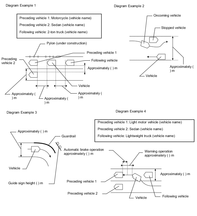
Result Proceed to NEXT
NEXT
-
INSPECT AUXILIARY BATTERY VOLTAGE
-
Measure the auxiliary battery voltage with the power switch off.
Standard voltage 11 to 14 V (IG OFF) If the voltage is below 11 V, recharge or replace the auxiliary battery before proceeding.
Result Proceed to NEXT
NEXT
-
-
INSPECT MILLIMETER WAVE RADAR SENSOR ASSEMBLY (BEAM AXIS MISALIGNMENT READING)*
-
Adjust the reflector height.
-
Place the reflector.
-
Connect the GTS to the DLC3.
-
Turn the power switch on (IG).
-
Turn the GTS on.
-
Turn the cruise control switch (ON/OFF button) on.
-
Enter the following menus: Powertrain / Radar Cruise / Utility / Beam Axis Misalignment Reading.
-
Check the amount of misalignment and make a note.
Powertrain > Radar Cruise > UtilityTester Display Beam Axis Misalignment Reading Result Proceed to NEXT
NEXT
-
-
CHECK CAN COMMUNICATION SYSTEM*
-
Use the GTS to check if the CAN communication system is functioning normally.
for LHD: Click here
for RHD: Click here
Result Result Proceed to CAN communication system DTCs are not output A CAN communication system DTCs are output (for LHD) B CAN communication system DTCs are output (for RHD) C
B 
GO TO CAN COMMUNICATION SYSTEM Click here
C
GO TO CAN COMMUNICATION SYSTEM Click here
A
-
-
CHECK FOR DTCs (PRE-CRASH 2)*
-
Clear the DTCs.
Body Electrical > Pre-Crash 2 > Clear DTCs -
Check for DTCs.
Body Electrical > Pre-Crash 2 > Trouble CodesResult Result Proceed to DTCs are not output (symptoms can be confirmed or reproduced) A DTCs are not output (symptoms cannot be confirmed or reproduced) B DTCs are output C
B 
GO TO STEP 8 Click here
C
GO TO DIAGNOSTIC TROUBLE CODE CHART Click here
A
-
-
PROBLEM SYMPTOMS TABLE
Result Result Proceed to Fault is not listed in problem symptoms table A Fault is listed in problem symptoms table B
B
ADJUST, REPAIR OR REPLACE IN ACCORDANCE WITH PROBLEM SYMPTOMS TABLE
A
-
OVERALL ANALYSIS AND TROUBLESHOOTING*
-
Terminals of ECU
-
Data List / Active Test
Result Proceed to NEXT
NEXT
-
-
ADJUST, REPAIR OR REPLACE
Tech Tips
Perform proper procedures according to corresponding faults listed in the problem symptoms table or the corresponding DTCs listed in the diagnostic trouble code chart.
Result Proceed to NEXT Note
-
If the millimeter wave radar sensor assembly is replaced, the beam axis of the sensor needs to be adjusted.
-
If the driving support ECU assembly is replaced, initialization needs to be performed.
for LHD: Click here
for RHD: Click here
NEXT
-
-
CONFIRMATION TEST
Result Proceed to NEXT
NEXT
END