METER / GAUGE SYSTEM FC System Indicator Malfunction
DESCRIPTION
In this circuit, the combination meter assembly receives FC system indicator signals from the EV control ECU via the CAN communication system. The combination meter assembly displays the FC system indicator based on the data received from the EV control ECU.
WIRING DIAGRAM
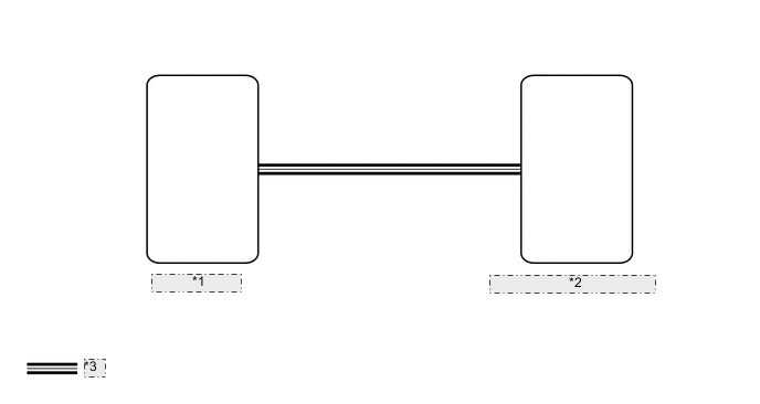
| *1 | EV Control ECU |
| *2 | Combination Meter Assembly |
| *3 | CAN Communication Line |
CAUTION / NOTICE / HINT
Note
When it is necessary to replace the combination meter assembly, be sure to replace it with a new one.
PROCEDURE
-
CHECK FOR DTC (CAN COMMUNICATION SYSTEM)
-
Check for DTCs.
for LHD: Click here
for RHD: Click here
OK No DTCs are output. Result Result Proceed to OK A NG (for LHD) B NG (for RHD) C
B 
GO TO CAN COMMUNICATION SYSTEM Click here
C
GO TO CAN COMMUNICATION SYSTEM Click here
A 
-
-
CHECK FOR DTC (HYBRID CONTROL SYSTEM)
-
Check for DTCs.
Powertrain > EV > Trouble CodesOK No DTCs are output. Result Proceed to OK NG
NG
GO TO HYBRID CONTROL SYSTEM Click here
OK
-
-
READ VALUE USING GTS (HV SYSTEM INDICATOR)
-
Using the GTSs, read the Data List.
Body Electrical > Combination Meter > Data ListTester Display Measurement Item Normal Condition Reference Value Diagnostic Note HV System Indicator FC system indicator value Min.: -100 %, Max.:511 % -100 to 511 % -
Body Electrical > Combination Meter > Data ListTester Display HV System Indicator OK FC system indicator value displayed on the GTS is almost the same as HV system indicator indication. Result Proceed to OK NG
NG
GO TO HYBRID CONTROL SYSTEM Click here
OK
-
-
CHECK COMBINATION METER ASSEMBLY
-
Replace the combination meter assembly.
-
Check that the operation of the FC system indicator returns to normal.
OK The operation of the FC system indicator returns to normal. Result Proceed to OK NG
OK
END (COMBINATION METER ASSEMBLY IS DEFECTIVE)
NG
REPLACE EV CONTROL ECU Click here
-