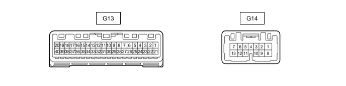
METER / GAUGE SYSTEM TERMINALS OF ECU
-
COMBINATION METER ASSEMBLY
-
Measure the voltage, resistance and waveform according to the value(s) in the table below.
Terminal No. (Symbol) Wiring Color Terminal Description Condition Specified Condition G13-1 (MSM+) - Body ground Y - Body ground Steering pad switch assembly signal Power switch on (IG), enter, top and back switches on steering pad switch assembly not pushed 4.8 to 5.2 V Power switch on (IG), enter, top or back switches on steering pad switch assembly pushed Below 1 V G13-2 (MSTI) - Body ground SB - Body ground Steering pad switch assembly signal Power switch on (IG), up, down, right, and left switches on steering pad switch assembly not pushed 4.8 to 5.2 V Power switch on (IG), up, down, right, or left switches on steering pad switch assembly pushed Below 1 V G13-4 (FCSI) - Body ground B - Body ground FC water release switch signal Power switch on (IG), FC water release switch not pushed Below 1 V Power switch on (IG), FC water release switch pushed 11 to 14 V G13-19 (+S) - Body ground L - Body ground Speed signal for other system (Output) Driving at approximately 20 km/h (12 mph) Pulse generation (See waveform 1) G13-20 (SI) - Body ground R - Body ground Speed signal for other system (Input) Driving at approximately 20 km/h (12 mph) Pulse generation (See waveform 1) G13-21 (IG+) - Body ground BE - Body ground Power switch signal Power switch off Below 1 V Power switch on (IG) 11 to 14 V G13-22 (B) - Body ground GR - Body ground Battery Power switch off 11 to 14 V G13-24 (TR) - Body ground B - Body ground Light control rheostat signal Power switch on (IG), up switch and down switch of light control rheostat not pushed 4.6 to 5.3 V Power switch on (IG), up switch of light control rheostat pushed Below 1 V G13-25 (TC) - Body ground V - Body ground Light control rheostat signal Power switch on (IG), up switch and down switch of light control rheostat not pushed 4.6 to 5.3 V Power switch on (IG), up switch and down switch of light control rheostat pushed Below 1 V G13-26 (CANH) - Body ground B - Body ground CAN communication line - - G13-27 (CANL) - Body ground W - Body ground CAN communication line - - G13-28 (ES) - Body ground BR - Body ground Ground Always Below 1 Ω G13-6 (INT) - Body ground B - Body ground Tire pressure warning reset switch Power switch on (IG), tire pressure warning reset switch off 8 to 15 V Power switch on (IG), tire pressure warning reset switch on Below 1 V G13-39 (ILL-) - Body ground W - Body ground Illumination signal Power switch on (IG), headlight dimmer switch off 11 to 14 V Power switch on (IG), headlight dimmer switch in tail or head position Below 1 V G13-40 (EP) - Body ground W-B - Body ground Ground Always Below 1 Ω G14-1 (B) - Body ground P - Body ground Battery Power switch off 11 to 14 V G14-10 (HAZ) - Body ground R - Body ground Hazard warning switch signal (Input) Power switch on (IG), hazard warning switch not pressed 11 to 14 V Power switch on (IG), hazard warning switch pressed Below 1 V G14-5 (ER) - Body ground G - Body ground RH turn indicator light signal (Input) Power switch on (IG), RH turn signal switch off 11 to 14 V Power switch on (IG), RH turn signal switch on Below 1 V G14-11 (EL) - Body ground SB - Body ground LH turn indicator light signal (Input) Power switch on (IG), LH turn signal switch off 11 to 14 V Power switch on (IG), LH turn signal switch on Below 1 V G14-7 (TRNR) - Body ground GR - Body ground RH turn indicator light signal (Output) Power switch on (IG), RH turn indicator light off Below 1 V Power switch on (IG), RH turn indicator light blinking 11 to 14 V ←→ Below 1 V G14-6 (LR) - Body ground L - Body ground RH turn indicator light signal (Output) Power switch on (IG), RH turn indicator light off Below 1 V Power switch on (IG), RH turn indicator light blinking 11 to 14 V ←→ Below 1 V G14-2 (LP) - Body ground G - Body ground Security indicator light signal Security indicator light off Below 1 V Security indicator light blinking 11 to 14 V ←→ Below 1 V G14-9 (SW) - Body ground V - Body ground Headlight dimmer switch assembly (full turn) signal Headlight dimmer switch assembly on (full turn) 11 to 14 V Headlight dimmer switch assembly off Below 1 V G13-34 (MSCL) - Body ground SB - Body ground CAN communication line - - G13-33 (MSCH) - Body ground GR - Body ground CAN communication line - - G14-13 (TRNL) - Body ground Y - Body ground LH turn indicator light signal (Output) Power switch on (IG), LH turn indicator light off Below 1 V Power switch on (IG), LH turn indicator light blinking 11 to 14 V ←→ Below 1 V G14-12 (LL) - Body ground B - Body ground LH turn indicator light signal (Output) Power switch on (IG), LH turn indicator light off Below 1 V Power switch on (IG), LH turn indicator light blinking 11 to 14 V ←→ Below 1 V G14-3 (PAON) - Body ground R - Body ground Passenger airbag ON indicator light signal Power switch on (IG), occupant detection sensor on 11 to 14 V G14-4 (P-AB) - Body ground B - Body ground Passenger airbag OFF indicatorlight signal Power switch on (IG), occupant detection sensor off Below 1 V
-
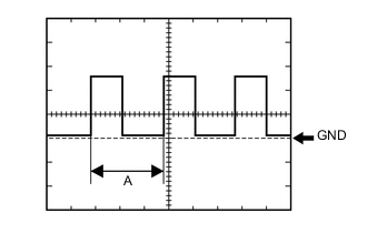
Using an oscilloscope, check waveform 1.
Waveform 1 (Reference) Item Condition Tester Connection
-
G13-19 (+S) - Body ground
-
G13-20 (SI) - Body ground
Tool setting 5 V/DIV., 20 ms./DIV. Vehicle condition Driving at approximately 20 km/h (12 mph) Tech Tips
When the system is functioning normally, one wheel revolution generates 4 pulses. As the vehicle speed increases, the width indicated by (A) in the illustration narrows.
-
-
-