THEFT DETERRENT SYSTEM Some Alarm Functions do not Operate
DESCRIPTION
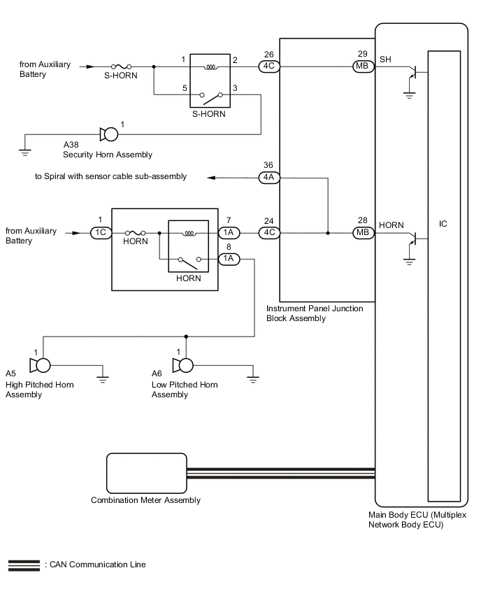
When the alarm sounds, the following alarm functions operate: the hazard lights flash, and the security horn and vehicle horns sound intermittently.
WIRING DIAGRAM
CAUTION / NOTICE / HINT
Note
-
Before replacing the main body ECU (multiplex network body ECU), refer to Service Bulletin.
-
Inspect the fuses for circuits related to this system before performing the following procedure.
PROCEDURE
-
CHECK THEFT DETERRENT SYSTEM OPERATION
-
Open the driver side window.
-
Set the theft deterrent system.
-
Close all doors, the luggage compartment door and hood.
-
Lock the doors using, wireless operation or entry operation.
-
Wait for 30 seconds or more.
-
-
Unlock the driver door using the door lock knob.
-
After 30 seconds have elapsed, check that the security indicator light changes from illuminated to flashing.
-
Check that each alarm component operates correctly.
Result Result Proceed to Security horn is not activated A Vehicle horn is not activated B Hazard lights are not activated C
B 
CHECK HORN OPERATION Click here
C 
GO TO LIGHTING SYSTEM Click here
A 
-
-
PERFORM ACTIVE TEST USING GTS (SECURITY HORN)
-
Connect the GTS to the DLC3.
-
Turn the power switch on (IG).
-
Turn the GTS on.
-
Enter the following menus: Body Electrical / Main Body / Active Test.
-
Perform the Active Test according to the display on the GTS.
Body Electrical > Main Body > Active TestTester Display Measurement Item Control Range Diagnostic Note Security Horn Security horn assembly OFF/ON -
Body Electrical > Main Body > Active TestTester Display Security Horn OK The security horn assembly sounds and stops correctly when operated through the GTS. Result Result Proceed to OK (for LHD) A OK (for RHD) B NG C
A
REPLACE MAIN BODY ECU (MULTIPLEX NETWORK BODY ECU) Click here
B
REPLACE MAIN BODY ECU (MULTIPLEX NETWORK BODY ECU) Click here
C
-
-
INSPECT S-HORN RELAY
-
Remove the S-HORN relay from the motor compartment relay block LH.
-
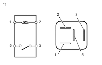
*1 S-HORN Relay Measure the resistance according to the value(s) in the table below.
Standard Resistance Tester Connection Condition Specified Condition 3 - 5 When battery voltage is not applied between terminals 1 and 2 10 kΩ or higher 3 - 5 When battery voltage is applied between terminals 1 and 2 Below 1 Ω Result Proceed to OK NG
NG
REPLACE S-HORN RELAY
OK
-
-
CHECK HARNESS AND CONNECTOR (AUXILIARY BATTERY - S-HORN RELAY)
-
Remove the S-HORN relay from the motor compartment relay block LH.
-
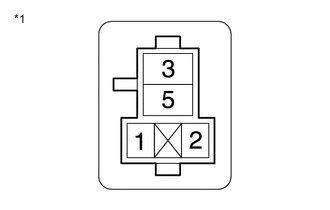
*1 Motor compartment relay block LH Measure the voltage according to the value(s) in the table below.
Standard Voltage Tester Connection Condition Specified Condition 1 (S-HORN relay holder) - Body ground Power switch off 11 to 14 V 5 (S-HORN relay holder) - Body ground Power switch off 11 to 14 V Result Proceed to OK NG
NG
REPAIR OR REPLACE HARNESS OR CONNECTOR
OK
-
-
INSPECT SECURITY HORN ASSEMBLY
-
Remove the security horn assembly.
for LHD: Click here
for RHD: Click here
-
Inspect the security horn assembly.
for LHD: Click here
for RHD: Click here
Result Result Proceed to OK A NG (for LHD) B NG (for RHD) C
B
REPLACE SECURITY HORN ASSEMBLY Click here
C
REPLACE SECURITY HORN ASSEMBLY Click here
A
-
-
CHECK HARNESS AND CONNECTOR (S-HORN RELAY - SECURITY HORN ASSEMBLY)
-
Remove the S-HORN relay from the motor compartment relay block LH.
-
Disconnect the A38 security horn assembly connector.
-
Measure the resistance according to the value(s) in the table below.
Standard Resistance Tester Connection Condition Specified Condition 3 (S-HORN relay holder) - A38-1 Always Below 1 Ω 3 (S-HORN relay holder) or A38-1 - Body ground Always 10 kΩ or higher Result Proceed to OK NG
NG
REPAIR OR REPLACE HARNESS OR CONNECTOR
OK
-
-
CHECK HARNESS AND CONNECTOR (S-HORN RELAY - INSTRUMENT PANEL JUNCTION BLOCK ASSEMBLY)
-
Remove the S-HORN relay from the motor compartment relay block LH.
-
Disconnect the 4C instrument panel junction block assembly connector.
-
Measure the resistance according to the value(s) in the table below.
Standard Resistance Tester Connection Condition Specified Condition 2 (S-HORN relay holder) - 4C-26 Always Below 1 Ω 2 (S-HORN relay holder) or 4C-26 - Body ground Always 10 kΩ or higher Result Proceed to OK NG
NG
REPAIR OR REPLACE HARNESS OR CONNECTOR
OK
-
-
INSPECT INSTRUMENT PANEL JUNCTION BLOCK ASSEMBLY
-
Remove the main body ECU (multiplex network body ECU).
for LHD: Click here
for RHD: Click here
-
Disconnect the instrument panel junction block assembly connector.
-
Measure the resistance according to the value(s) in the table below.
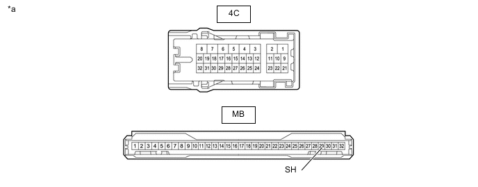
*a Component without harness connected
(Instrument panel junction block assembly)
- - Standard Resistance Tester Connection Condition Specified Condition 4C-26 - MB-29 (SH) Always Below 1 Ω Result Result Proceed to OK (for LHD) A OK (for RHD) B NG (for LHD) C NG (for RHD) D
A
REPLACE MAIN BODY ECU (MULTIPLEX NETWORK BODY ECU) Click here
B
REPLACE MAIN BODY ECU (MULTIPLEX NETWORK BODY ECU) Click here
C
REPLACE INSTRUMENT PANEL JUNCTION BLOCK ASSEMBLY Click here
D
REPLACE INSTRUMENT PANEL JUNCTION BLOCK ASSEMBLY Click here
-
-
CHECK HORN OPERATION
-
Press the horn switch and check if the horn sounds.
OK Horn sounds Result Proceed to OK NG
NG
GO TO HORN SYSTEM Click here
OK
-
-
INSPECT INSTRUMENT PANEL JUNCTION BLOCK ASSEMBLY
-
Remove the main body ECU (multiplex network body ECU).
for LHD: Click here
for RHD: Click here
-
Disconnect the instrument panel junction block assembly connector.
-
Measure the resistance according to the value(s) in the table below.
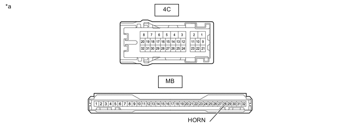
*a Component without harness connected
(Instrument panel junction block assembly)
- - Standard Resistance Tester Connection Condition Specified Condition 4C-24 - MB-28 (HORN) Always Below 1 Ω Result Result Proceed to OK (for LHD) A OK (for RHD) B NG (for LHD) C NG (for RHD) D
A
REPLACE MAIN BODY ECU (MULTIPLEX NETWORK BODY ECU) Click here
B
REPLACE MAIN BODY ECU (MULTIPLEX NETWORK BODY ECU) Click here
C
REPLACE INSTRUMENT PANEL JUNCTION BLOCK ASSEMBLY Click here
D
REPLACE INSTRUMENT PANEL JUNCTION BLOCK ASSEMBLY Click here
-