THEFT DETERRENT SYSTEM While Alarm is Armed, Luggage Door or Hood is opened but Alarm does not Sound
DESCRIPTION
A situation in which the alarm is armed but does not sound when the luggage compartment door or hood is opened can be caused when the main body ECU (multiplex network body ECU) cannot detect whether the luggage compartment door courtesy, hood courtesy switch is open or closed.
If the alarm does not sound, there may be a malfunction in the luggage compartment door courtesy, hood courtesy switch, main body ECU (multiplex network body ECU) or a wire harness.
WIRING DIAGRAM
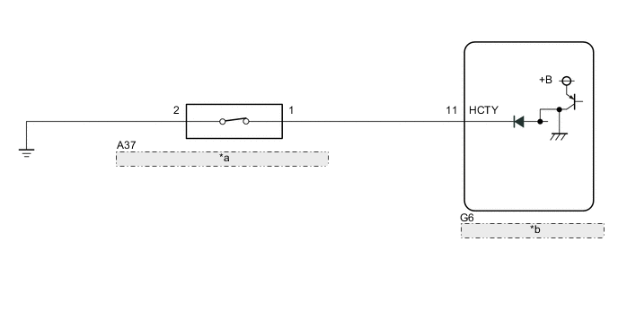
| *a | Hood Lock Assembly (Hood Courtesy Switch) |
| *b | Main Body ECU (Multiplex Network Body ECU) |
CAUTION / NOTICE / HINT
Note
Before replacing the main body ECU (multiplex network body ECU), refer to Service Bulletin.
PROCEDURE
-
CHECK SECURITY INDICATOR LIGHT OPERATION
-
Close all doors, the luggage compartment door and hood.
-
Lock the doors using the, wireless operation or entry operation.
-
Check that the security indicator light illuminates.
-
After 30 seconds have elapsed, check that the security indicator light changes from illuminated to flashing.
Tech Tips
The illumination status of the security indicator light can be used to determine whether the theft deterrent system is set or unset.
Result Proceed to OK NG
NG 
GO TO THEFT DETERRENT SYSTEM CANNOT BE SET OR UNSET Click here
OK 
-
-
READ VALUE USING GTS (HOOD COURTESY SW)
-
Connect the GTS to the DLC3.
-
Turn the power switch on (IG).
-
Turn the GTS on.
-
Enter the following menus: Body Electrical / Main Body / Data List.
-
Read the Data List according to the display on the GTS.
Body Electrical > Main Body > Data ListTester Display Measurement Item Range Normal Condition Diagnostic Note Hood Courtesy SW Hood courtesy switch ON or OFF ON: Hood open
OFF: Hood closed
-
Body Electrical > Main Body > Data ListTester Display Hood Courtesy SW OK The GTS display changes correctly in response to the hood courtesy switch (hood lock assembly) status. Result Result Proceed to OK (for LHD) A OK (for RHD) B NG C
A
REPLACE MAIN BODY ECU (MULTIPLEX NETWORK BODY ECU) Click here
B
REPLACE MAIN BODY ECU (MULTIPLEX NETWORK BODY ECU) Click here
C
-
-
INSPECT HOOD LOCK ASSEMBLY
-
Remove the hood lock assembly.
-
Inspect the hood lock assembly.
Result Proceed to OK NG
NG
REPLACE HOOD LOCK ASSEMBLY Click here
OK
-
-
CHECK HARNESS AND CONNECTOR (HOOD LOCK ASSEMBLY - MAIN BODY ECU (MULTIPLEX NETWORK BODY ECU))
-
Disconnect the A37 hood lock assembly connector.
-
Disconnect the G6 main body ECU (multiplex network body ECU) connector.
-
Measure the resistance according to the value(s) in the table below.
Standard Resistance Tester Connection Condition Specified Condition A37-1 - G6-11 (HCTY) Always Below 1 Ω A37-2 - Body ground Always Below 1 Ω A37-1 or G6-11 (HCTY) - Body ground Always 10 kΩ or higher Result Proceed to OK NG
NG
REPAIR OR REPLACE HARNESS OR CONNECTOR
OK
-
-
READ VALUE USING GTS (LUGGAGE COURTESY SW)
-
Connect the GTS to the DLC3.
-
Turn the power switch on (IG).
-
Turn the GTS on.
-
Enter the following menus: Body Electrical / Main Body / Data List.
-
Read the Data List according to the display on the GTS.
Body Electrical > Main Body > Data ListTester Display Measurement Item Range Normal Condition Diagnostic Note Luggage Courtesy SW Luggage compartment door courtesy switch ON or OFF ON: Luggage compartment door open
OFF: Luggage compartment door closed
-
Body Electrical > Main Body > Data ListTester Display Luggage Courtesy SW OK The GTS display changes correctly in response to the luggage compartment door courtesy switch status. Result Result Proceed to OK (for LHD) A OK (for RHD) B NG C
A
REPLACE MAIN BODY ECU (MULTIPLEX NETWORK BODY ECU) Click here
B
REPLACE MAIN BODY ECU (MULTIPLEX NETWORK BODY ECU) Click here
C
-
-
INSPECT LUGGAGE COMPARTMENT DOOR LOCK ASSEMBLY
-
Remove the luggage compartment door lock assembly.
-
Inspect the luggage compartment door lock assembly.
Result Proceed to OK NG
NG
REPLACE LUGGAGE COMPARTMENT DOOR LOCK ASSEMBLY Click here
OK
-
-
CHECK HARNESS AND CONNECTOR (LUGGAGE COMPARTMENT DOOR LOCK ASSEMBLY - INSTRUMENT PANEL JUNCTION BLOCK ASSEMBLY)
-
Disconnect the P27 luggage compartment door lock assembly connector.
-
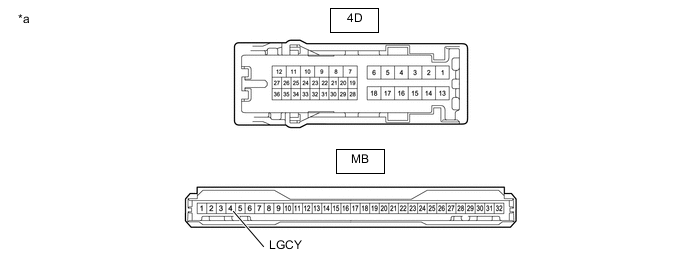
Disconnect the 4D instrument panel junction block assembly connector.
-
Measure the resistance according to the value(s) in the table below.
Standard Resistance Tester Connection Condition Specified Condition P27-3 (D+) - 4D-16 Always Below 1 Ω P27-2 (E) - Body ground Always Below 1 Ω P27-3 (D+) or 4D-16 - Body ground Always 10 kΩ or higher Result Proceed to OK NG
NG
REPAIR OR REPLACE HARNESS OR CONNECTOR
OK
-
-
INSPECT INSTRUMENT PANEL JUNCTION BLOCK ASSEMBLY
-
Remove the instrument panel junction block assembly.
for LHD: Click here
for RHD: Click here
-
Remove the main body ECU (multiplex network body ECU) from the instrument panel junction block assembly.
*a Component without harness connected
(Instrument Panel Junction Block Assembly)
- - -
Measure the resistance according to the value(s) in the table below.
Standard Resistance Tester Connection Condition Specified Condition MB-4 (LGCY) - 4D-16 Always Below 1 Ω Result Result Proceed to OK (for LHD) A OK (for RHD) B NG (for LHD) C NG (for RHD) D
A
REPLACE MAIN BODY ECU (MULTIPLEX NETWORK BODY ECU) Click here
B
REPLACE MAIN BODY ECU (MULTIPLEX NETWORK BODY ECU) Click here
C
REPLACE INSTRUMENT PANEL JUNCTION BLOCK ASSEMBLY Click here
D
REPLACE INSTRUMENT PANEL JUNCTION BLOCK ASSEMBLY Click here
-