THEFT DETERRENT SYSTEM TERMINALS OF ECU
-
CHECK MAIN BODY ECU (MULTIPLEX NETWORK BODY ECU) AND INSTRUMENT PANEL JUNCTION BLOCK ASSEMBLY
-
Remove the main body ECU (multiplex network body ECU) from instrument panel junction block assembly.
for LHD: Click here
for RHD: Click here
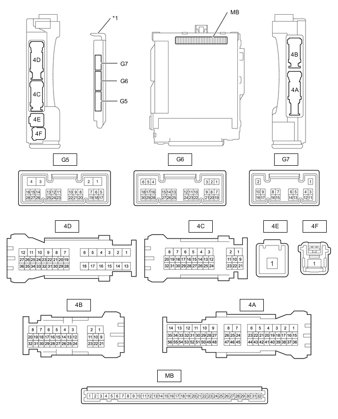
*1 Main Body ECU (Multiplex Network Body ECU) - - -
Reconnect the instrument panel junction block assembly connectors.
-
Measure the resistance and voltage according to the value(s) in the table below.
Tech Tips
Measure the values on the wire harness side with the connector disconnected.
Tester Connection Wiring Color Terminal Description Condition Specified Condition MB-31 (BECU) - Body ground - +B power supply Power switch off 11 to 14 V MB-32 (IG) - Body ground - IG power supply (IG signal) Power switch on (IG) → off 11 to 14 V → Below 1 V MB-30 (ACC) - Body ground - ACC power supply (ACC signal) Power switch on (ACC) → off 11 to 14 V → Below 1 V MB-11 (GND1) - Body ground - Ground Always Below 1 Ω G6-6 (FLCY) - Body ground P - Body ground Front door courtesy light switch assembly (for LH) input Front door LH closed (OFF) → open (ON) 10 kΩ or higher → Below 1 Ω G6-27 (FRCY) - Body ground L - Body ground Front door courtesy light switch assembly (for RH) input Front door RH closed (OFF) → open (ON) 10 kΩ or higher → Below 1 Ω MB-13 (LCTY) - Body ground - Rear door courtesy light switch assembly (for LH) input Rear door LH closed (OFF) → open (ON) 10 kΩ or higher → Below 1 Ω MB-2 (RCTY) - Body ground - Rear door courtesy light switch assembly (for RH) input Rear door RH closed (OFF) → open (ON) 10 kΩ or higher → Below 1 Ω MB-4 (LGCY) - Body ground - Luggage compartment door courtesy light switch input Luggage compartment door closed (OFF) → open (ON) 10 kΩ or higher → Below 1 Ω G6-11 (HCTY) - Body ground W - Body ground Hood courtesy switch input Hood open (OFF) → closed (ON) 10 kΩ or higher → Below 1 Ω G6-18 (TKUL) - Body ground L - Body ground Luggage compartment door unlock switch input Luggage compartment door lock key cylinder in neutral position → unlock position 10 kΩ or higher → Below 1 Ω If the result is not as specified, there may be a malfunction in the wire harness.
-
Install the main body ECU (multiplex network body ECU) to instrument panel junction block assembly.
for LHD: Click here
for RHD: Click here
-
Measure the voltage and check for pulses according to the value(s) in the table below.
Tester Connection Wiring Color Terminal Description Condition Specified Condition 4B-26 (LSFL) - Body ground P - Body ground Front door LH unlock detection switch input Front door LH unlocked Below 1 V Front door LH locked Pulse generation 4B-27 (LSFR) - Body ground LG - Body ground Front door RH unlock detection switch input Front door RH unlocked Below 1 V Front door RH locked Pulse generation 4B-23 (LSWL) - Body ground GR - Body ground Rear door LH unlock detection switch input Rear door LH unlocked Below 1 V Rear door LH locked Pulse generation G5-2 (LSWR) - Body ground Y - Body ground Rear door RH unlock detection switch input Rear door RH unlocked Below 1 V Rear door RH locked Pulse generation 4C-26 (SH) - Body ground L - Body ground Security horn assembly drive Security horn assembly sounding
(Theft deterrent system is in alarm sounding state)
Pulse generation
(Below 1 V ← → 11 to 14 V)
4C-24 (HORN) - Body ground B - Body ground Vehicle horns drive Vehicle horns sounding
(Theft deterrent system is in alarm sounding state)
Pulse generation
(Below 1 V ← → 11 to 14 V)
If the result is not as specified, the main body ECU (multiplex network body ECU) may be malfunctioning.
-