WIRELESS DOOR LOCK CONTROL SYSTEM DIAGNOSIS SYSTEM
-
DESCRIPTION
The ECU stores DTCs when malfunctions occur.
The diagnostic system allows for reading of the DTCs from the DLC3.
Use the GTS to check for malfunctions and perform repairs.
-
CHECK DLC3
-
Check the DLC3.
-
-
INSPECT AUXILIARY BATTERY VOLTAGE
-
Measure the auxiliary battery voltage.
If the voltage is below 11 V, recharge or replace the auxiliary battery.
-
-
SELF-DIAGNOSTIC MODE (USING GTS)
-
Connect the GTS to the DLC3.
-
Turn the power switch on (IG).
-
Turn the GTS on.
-
Enter the following menus: Body Electrical / Entry&Start / Utility / Wireless Door Lock Diagnosis Mode.
Body Electrical > Entry&Start > UtilityTester Display Wireless Door Lock Diagnosis Mode -
Proceed to the next step in accordance with the prompts on the GTS screen.
-
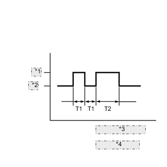
Wireless Door Lock Buzzer Output *1 ON *2 OFF *3 T1: 0.125 seconds *4 T2: 0.5 seconds Check that the system has switched to self-diagnostic mode by checking the wireless door lock buzzer output pattern.
-
Check the diagnostic outputs when an electrical key transmitter sub-assembly switch is pressed. The diagnostic outputs can be checked by the interior light and wireless door lock buzzer patterns.
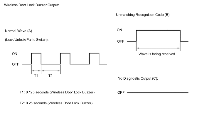
Result Wireless Door Lock Buzzer Output Suspected Area A Normal (No malfunction) B Register wireless code C Wave interference or malfunction of a related component
-