CAN COMMUNICATION SYSTEM(for LHD) SYSTEM DIAGRAM
-
OVERALL CAN BUS DIAGRAM
-
The CAN communication system is composed of 3 buses.
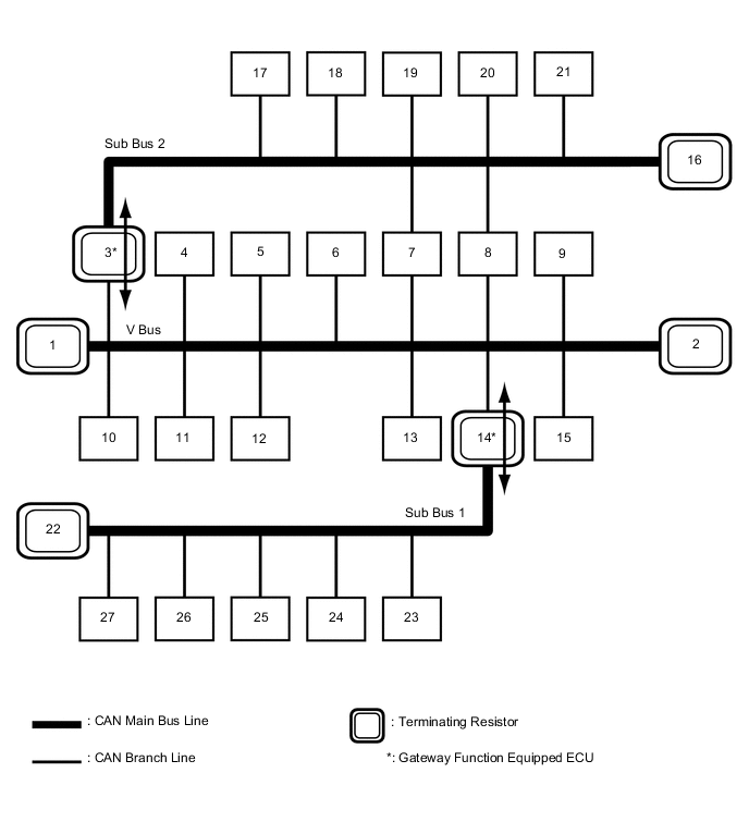
1 Combination Meter Assembly
(for V Bus)
2 FC Converter Assembly
(for V Bus)
3 Network Gateway ECU
(for V Bus and Sub Bus 2)
4 Certification ECU (Smart Key ECU Assembly)
(for V Bus)
5 Radio and Display Receiver Assembly
(for V Bus)
6 Power Steering ECU Assembly
(for V Bus)
7 Skid Control ECU (Brake Booster with Master Cylinder Assembly)
(for V Bus and Sub Bus 2)
8 EV Control ECU
(for V Bus and Sub Bus 2)
9 Airbag ECU Assembly
(for V Bus)
10 FC Control ECU
(for V Bus)
11 Spiral Cable with Sensor Sub-assembly
(for V Bus)
12 DLC3
(for V Bus)
13 Integration Control and Panel Assembly
(for V Bus)
14 Main Body ECU (Multiplex Network Body ECU)
(for V Bus and Sub Bus 1)
15 Air Conditioning Amplifier Assembly
(for V Bus)
16 No. 2 CAN Junction Terminal
(for Sub Bus 2)
17 Driving Support ECU Assembly
(for Sub Bus 2)
18 Transmission Control ECU Assembly
(for Sub Bus 2)
19 Clearance Warning ECU Assembly
(for Sub Bus 2)
20 Blind Spot Monitor Sensor RH
(for Sub Bus 2)
21 Lane Departure Warning Camera
(for Sub Bus 2)
22 No. 1 CAN Junction Terminal
(for Sub Bus 1)
23 Multiplex Tilt and Telescopic ECU
(for Sub Bus 1)
24 Outer Mirror Control ECU Assembly LH
(for Sub Bus 1)
25 Outer Mirror Control ECU Assembly RH
(for Sub Bus 1)
26 Headlight light control ECU sub-assembly LH
(for Sub Bus 1)
27 Position Control ECU and Switch Assembly
(for Sub Bus 1)
- - Tech Tips
-
The main body ECU (multiplex network body ECU) functions as a gateway between the V bus and sub bus 1.
-
The network gateway ECU functions as a gateway between the V bus and sub bus 2.
-
Refer to the following bus wiring diagrams for details.
-
-
-
V BUS
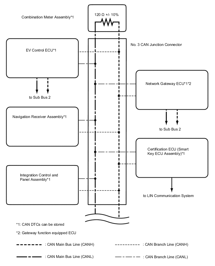
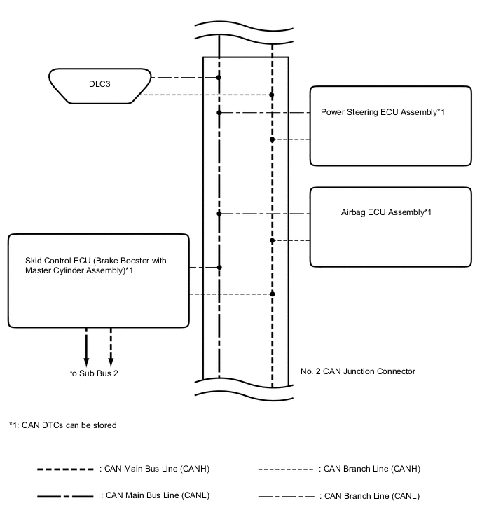
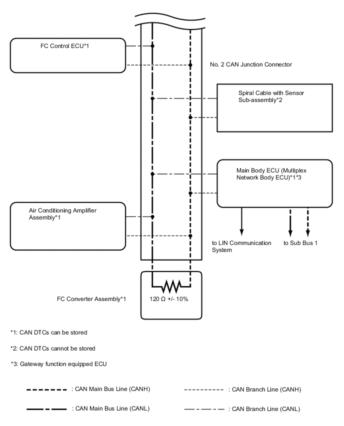
Tech Tips
The CAN communication system connects to other networks via ECUs that function as a gateway.
-
SUB BUS 1
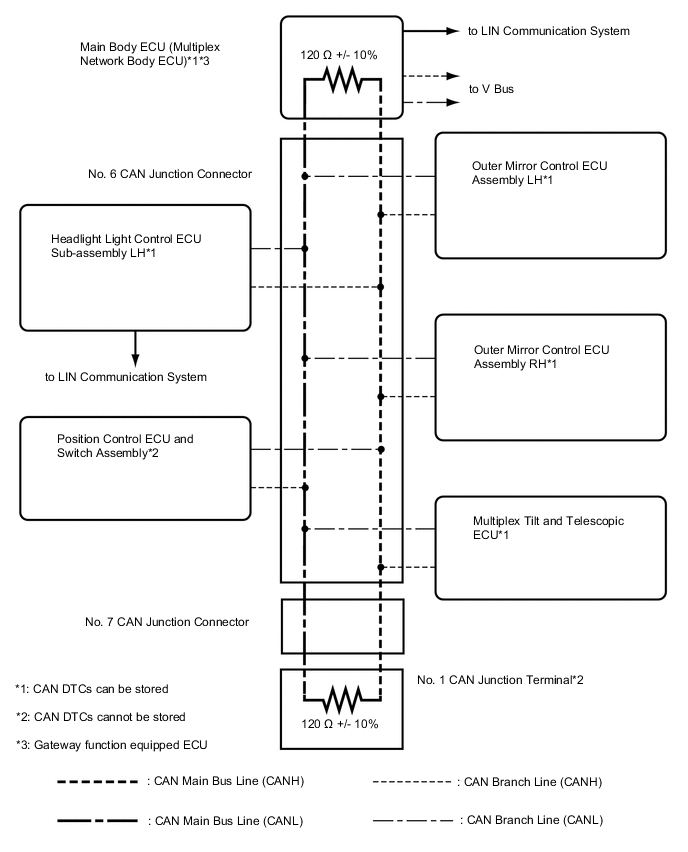
Tech Tips
The CAN communication system connects to other networks via ECUs that function as a gateway.
-
SUB BUS 2
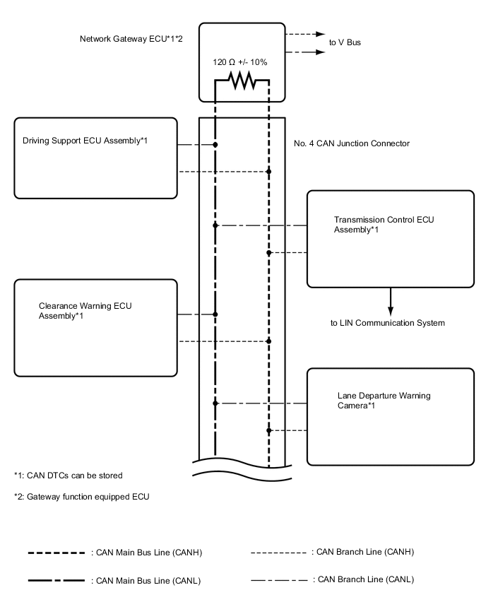
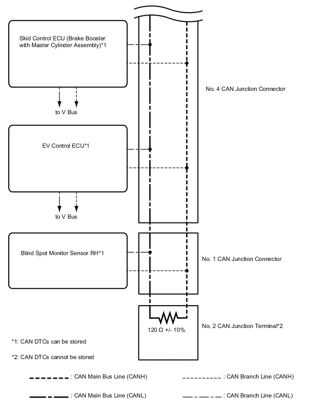
Tech Tips
The CAN communication system connects to other networks via ECUs that function as a gateway.
-
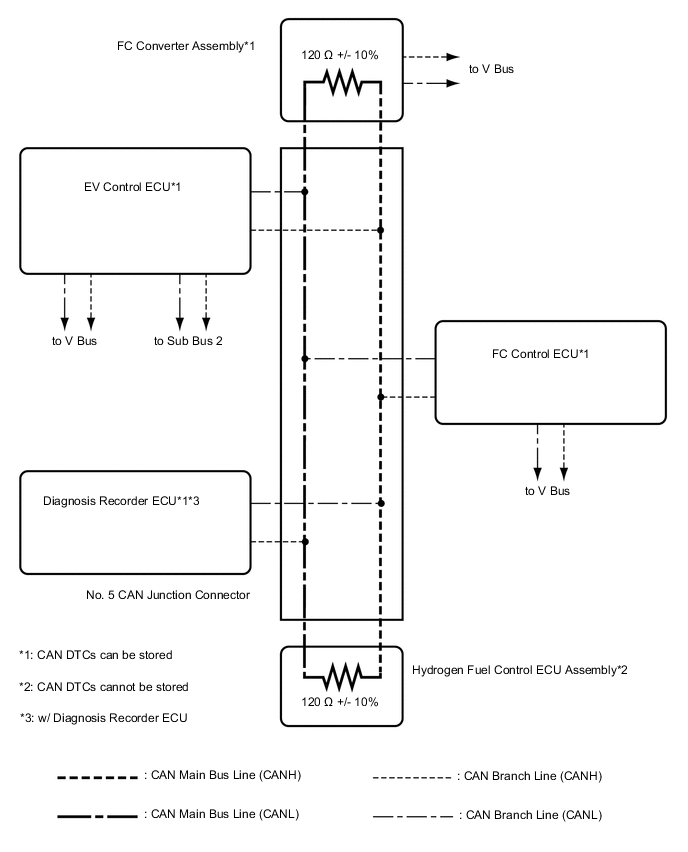
FC Local Bus