LIN COMMUNICATION SYSTEM, Diagnostic DTC:B2325
| DTC Code | DTC Name |
|---|---|
| B2325 | LIN Communication Bus Malfunction |
DESCRIPTION
The main body ECU (multiplex network body ECU) intermittently monitors the LIN communication bus between the components related to the doors and sliding roof drive gear sub-assembly. DTC B2325 is stored when a malfunction in the LIN communication bus between the components related to the doors and sliding roof drive gear sub-assembly is detected consecutively 3 times.
| DTC No. | Detection Item | DTC Detection Condition | Trouble Area |
|---|---|---|---|
| B2325 | LIN Communication Bus Malfunction | Main body ECU (multiplex network body ECU) detects errors in communication with the ECUs connected to the door bus lines 3 times in a row. |
|
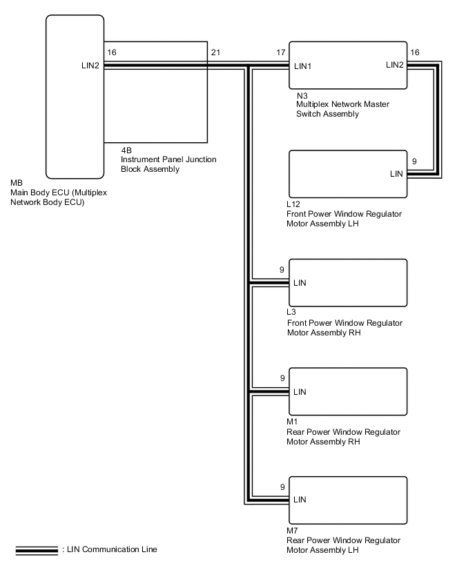
WIRING DIAGRAM
-
for LHD
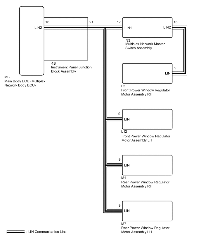
-
for RHD
CAUTION / NOTICE / HINT
Note
-
When using the GTS with the power switch off to troubleshoot:
Connect the GTS to the vehicle and turn a courtesy light switch on and off at 1.5 second intervals until communication between the GTS and vehicle begins.
-
When the power window regulator motor assembly is removed and reinstalled or replaced, the power window regulator motor assembly must be initialized.
-
If the main body ECU (multiplex network body ECU) is replaced, refer to the Service Bulletin.
Tech Tips
When DTC B2325 and a LIN communication stop DTC are output simultaneously, first perform troubleshooting for DTC B2325. Then perform troubleshooting for the LIN communication stop DTC.
PROCEDURE
-
CLEAR DTC
-
Clear the DTCs.
Body Electrical > Main Body > Clear DTCsResult Proceed to NEXT
NEXT 
-
-
CHECK FOR DTC
-
Check for DTCs.
Body Electrical > Main Body > Trouble CodesResult Result Proceed to DTC B2325 is not output A DTC B2325 is output B
A 
USE SIMULATION METHOD TO CHECK Click here
B
-
-
INSPECT MULTIPLEX NETWORK MASTER SWITCH ASSEMBLY
-
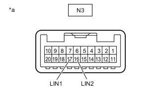
*a Component without harness connected
(Multiplex Network Master Switch Assembly)
Remove the multiplex network master switch assembly.
-
Measure the resistance according to the value(s) in the table below.
Standard Resistance Tester Connection Condition Specified Condition N3-16 (LIN2) - N3-17 (LIN1) Always Below 1 Ω Result Proceed to OK NG
NG
REPLACE MULTIPLEX NETWORK MASTER SWITCH ASSEMBLY Click here
OK
-
-
CHECK HARNESS AND CONNECTOR (MULTIPLEX NETWORK MASTER SWITCH ASSEMBLY - FRONT POWER WINDOW REGULATOR MOTOR ASSEMBLY)
-
for LHD
-
Disconnect the N3 multiplex network master switch assembly connector.
-
Disconnect the L12 front power window regulator motor assembly LH connector.
-
Measure the resistance according to the value(s) in the table below.
Standard Resistance Tester Connection Condition Specified Condition N3-16 (LIN2) - L12-9 (LIN) Always Below 1 Ω N3-16 (LIN2) or L12-9 (LIN) - Body ground Always 10 kΩ or higher
-
-
for RHD
-
Disconnect the N3 multiplex network master switch assembly connector.
-
Disconnect the L3 front power window regulator motor assembly RH connector.
-
Measure the resistance according to the value(s) in the table below.
Standard Resistance Tester Connection Condition Specified Condition N3-16 (LIN2) - L3-9 (LIN) Always Below 1 Ω N3-16 (LIN2) or L3-9 (LIN) - Body ground Always 10 kΩ or higher
Result Proceed to OK NG -
NG
REPAIR OR REPLACE HARNESS OR CONNECTOR
OK
-
-
CHECK HARNESS AND CONNECTOR (MAIN BODY ECU (MULTIPLEX NETWORK BODY ECU) - MULTIPLEX NETWORK MASTER SWITCH ASSEMBLY)
-
for LHD
-
Remove the main body ECU (multiplex network body ECU) from the instrument panel junction block assembly.
-
Disconnect the N3 multiplex network master switch assembly connector.
-
Disconnect the L3 front power window regulator motor assembly RH connector.
-
Disconnect the M7 rear power window regulator motor assembly LH connector.
-
Disconnect the M1 rear power window regulator motor assembly RH connector.
-
Measure the resistance according to the value(s) in the table below.
Standard Resistance Tester Connection Condition Specified Condition MB-16 (LIN2) - N3-17 (LIN1) Always Below 1 Ω MB-16 (LIN2) or N3-17 (LIN1) - Body ground Always 10 kΩ or higher
-
-
for RHD
-
Remove the main body ECU (multiplex network body ECU) from the instrument panel junction block assembly.
-
Disconnect the N3 multiplex network master switch assembly connector.
-
Disconnect the L12 front power window regulator motor assembly LH connector.
-
Disconnect the M7 rear power window regulator motor assembly LH connector.
-
Disconnect the M1 rear power window regulator motor assembly RH connector.
-
Measure the resistance according to the value(s) in the table below.
Standard Resistance Tester Connection Condition Specified Condition MB-16 (LIN2) - N3-17 (LIN1) Always Below 1 Ω MB-16 (LIN2) or N3-17 (LIN1) - Body ground Always 10 kΩ or higher
Result Proceed to OK NG -
NG 
CHECK HARNESS AND CONNECTOR (INSTRUMENT PANEL JUNCTION BLOCK ASSEMBLY - MULTIPLEX NETWORK MASTER SWITCH ASSEMBLY) Click here
OK
-
-
CHECK HARNESS AND CONNECTOR (MAIN BODY ECU (MULTIPLEX NETWORK BODY ECU) - FRONT POWER WINDOW REGULATOR MOTOR ASSEMBLY)
-
for LHD
-
Remove the main body ECU (multiplex network body ECU) from the instrument panel junction block assembly.
-
Disconnect the N3 multiplex network master switch assembly connector.
-
Disconnect the L3 front power window regulator motor assembly RH connector.
-
Disconnect the M7 rear power window regulator motor assembly LH connector.
-
Disconnect the M1 rear power window regulator motor assembly RH connector.
-
Measure the resistance according to the value(s) in the table below.
Standard Resistance Tester Connection Condition Specified Condition MB-16 (LIN2) - L3-9 (LIN) Always Below 1 Ω MB-16 (LIN2) or L3-9 (LIN) - Body ground Always 10 kΩ or higher
-
-
for RHD
-
Remove the main body ECU (multiplex network body ECU) from the instrument panel junction block assembly.
-
Disconnect the N3 multiplex network master switch assembly connector.
-
Disconnect the L12 front power window regulator motor assembly LH connector.
-
Disconnect the M7 rear power window regulator motor assembly LH connector.
-
Disconnect the M1 rear power window regulator motor assembly RH connector.
-
Measure the resistance according to the value(s) in the table below.
Standard Resistance Tester Connection Condition Specified Condition MB-16 (LIN2) - L12-9 (LIN) Always Below 1 Ω MB-16 (LIN2) or L12-9 (LIN) - Body ground Always 10 kΩ or higher
Result Proceed to OK NG -
NG
CHECK HARNESS AND CONNECTOR (INSTRUMENT PANEL JUNCTION BLOCK ASSEMBLY - FRONT POWER WINDOW REGULATOR MOTOR ASSEMBLY) Click here
OK
-
-
CHECK HARNESS AND CONNECTOR (MAIN BODY ECU (MULTIPLEX NETWORK BODY ECU) - REAR POWER WINDOW REGULATOR MOTOR ASSEMBLY LH)
-
for LHD
-
Remove the main body ECU (multiplex network body ECU) from the instrument panel junction block assembly.
-
Disconnect the N3 multiplex network master switch assembly connector.
-
Disconnect the L3 front power window regulator motor assembly RH connector.
-
Disconnect the M7 rear power window regulator motor assembly LH connector.
-
Disconnect the M1 rear power window regulator motor assembly RH connector.
-
Measure the resistance according to the value(s) in the table below.
Standard Resistance Tester Connection Condition Specified Condition MB-16 (LIN2) - M7-9 (LIN) Always Below 1 Ω MB-16 (LIN2) or M7-9 (LIN) - Body ground Always 10 kΩ or higher
-
-
for RHD
-
Remove the main body ECU (multiplex network body ECU) from the instrument panel junction block assembly.
-
Disconnect the N3 multiplex network master switch assembly connector.
-
Disconnect the L12 front power window regulator motor assembly LH connector.
-
Disconnect the M7 rear power window regulator motor assembly LH connector.
-
Disconnect the M1 rear power window regulator motor assembly RH connector.
-
Measure the resistance according to the value(s) in the table below.
Standard Resistance Tester Connection Condition Specified Condition MB-16 (LIN2) - M7-9 (LIN) Always Below 1 Ω MB-16 (LIN2) or M7-9 (LIN) - Body ground Always 10 kΩ or higher
Result Proceed to OK NG -
NG
CHECK HARNESS AND CONNECTOR (INSTRUMENT PANEL JUNCTION BLOCK ASSEMBLY - REAR POWER WINDOW REGULATOR MOTOR ASSEMBLY LH) Click here
OK
-
-
CHECK HARNESS AND CONNECTOR (MAIN BODY ECU (MULTIPLEX NETWORK BODY ECU) - REAR POWER WINDOW REGULATOR MOTOR ASSEMBLY RH)
-
for LHD
-
Remove the main body ECU (multiplex network body ECU) from the instrument panel junction block assembly.
-
Disconnect the N3 multiplex network master switch assembly connector.
-
Disconnect the L3 front power window regulator motor assembly RH connector.
-
Disconnect the M7 rear power window regulator motor assembly LH connector.
-
Disconnect the M1 rear power window regulator motor assembly RH connector.
-
Measure the resistance according to the value(s) in the table below.
Standard Resistance Tester Connection Condition Specified Condition MB-16 (LIN2) - M1-9 (LIN) Always Below 1 Ω MB-16 (LIN2) or M1-9 (LIN) - Body ground Always 10 kΩ or higher
-
-
for RHD
-
Remove the main body ECU (multiplex network body ECU) from the instrument panel junction block assembly.
-
Disconnect the N3 multiplex network master switch assembly connector.
-
Disconnect the L12 front power window regulator motor assembly LH connector.
-
Disconnect the M7 rear power window regulator motor assembly LH connector.
-
Disconnect the M1 rear power window regulator motor assembly RH connector.
-
Measure the resistance according to the value(s) in the table below.
Standard Resistance Tester Connection Condition Specified Condition MB-16 (LIN2) - M1-9 (LIN) Always Below 1 Ω MB-16 (LIN2) or M1-9 (LIN) - Body ground Always 10 kΩ or higher
Result Proceed to OK NG -
NG
CHECK HARNESS AND CONNECTOR (INSTRUMENT PANEL JUNCTION BLOCK ASSEMBLY - REAR POWER WINDOW REGULATOR MOTOR ASSEMBLY RH) Click here
OK
-
-
CHECK FOR DTC
-
Disconnect the N3 multiplex network master switch assembly connector.
-
Check for DTCs.
Body Electrical > Main Body > Trouble CodesResult Result Proceed to DTC B2325 is output A DTC B2325 is not output B
B
REPLACE MULTIPLEX NETWORK MASTER SWITCH ASSEMBLY Click here
A
-
-
CLEAR DTC
-
Clear the DTCs.
Body Electrical > Main Body > Clear DTCsResult Proceed to NEXT
NEXT
-
-
CHECK FOR DTC
-
Disconnect the L12 front power window regulator motor assembly LH connector.
-
Check for DTCs.
Body Electrical > Main Body > Trouble CodesResult Result Proceed to DTC B2325 is output A DTC B2325 is not output B
B
REPLACE FRONT POWER WINDOW REGULATOR MOTOR ASSEMBLY LH Click here
A
-
-
CLEAR DTC
-
Clear the DTCs.
Body Electrical > Main Body > Clear DTCsResult Proceed to NEXT
NEXT
-
-
CHECK FOR DTC
-
Disconnect the L3 front power window regulator motor assembly RH connector.
-
Check for DTCs.
Body Electrical > Main Body > Trouble CodesResult Result Proceed to DTC B2325 is output A DTC B2325 is not output B
B
REPLACE FRONT POWER WINDOW REGULATOR MOTOR ASSEMBLY RH Click here
A
-
-
CLEAR DTC
-
Clear the DTCs.
Body Electrical > Main Body > Clear DTCsResult Proceed to NEXT
NEXT
-
-
CHECK FOR DTC
-
Disconnect the M1 rear power window regulator motor assembly RH connector.
-
Check for DTCs.
Body Electrical > Main Body > Trouble CodesResult Result Proceed to DTC B2325 is output A DTC B2325 is not output B
B
REPLACE REAR POWER WINDOW REGULATOR MOTOR ASSEMBLY RH Click here
A
-
-
CLEAR DTC
-
Clear the DTCs.
Body Electrical > Main Body > Clear DTCsResult Proceed to NEXT
NEXT
-
-
CHECK FOR DTC
-
Disconnect the M7 rear power window regulator motor assembly LH connector.
-
Check for DTCs.
Body Electrical > Main Body > Trouble CodesResult Result Proceed to DTC B2325 is output (for LHD) A DTC B2325 is output (for RHD) B DTC B2325 is not output C
A
REPLACE MAIN BODY ECU (MULTIPLEX NETWORK BODY ECU) Click here
B
REPLACE MAIN BODY ECU (MULTIPLEX NETWORK BODY ECU) Click here
C
REPLACE REAR POWER WINDOW REGULATOR MOTOR ASSEMBLY LH Click here
-
-
CHECK HARNESS AND CONNECTOR (INSTRUMENT PANEL JUNCTION BLOCK ASSEMBLY - MULTIPLEX NETWORK MASTER SWITCH ASSEMBLY)
-
for LHD
-
Disconnect the 4B instrument panel junction block assembly connector.
-
Disconnect the N3 multiplex network master switch assembly connector.
-
Disconnect the L3 front power window regulator motor assembly RH connector.
-
Disconnect the M7 rear power window regulator motor assembly LH connector.
-
Disconnect the M1 rear power window regulator motor assembly RH connector.
-
Measure the resistance according to the value(s) in the table below.
Standard Resistance Tester Connection Condition Specified Condition 4B-21 - N3-17 (LIN1) Always Below 1 Ω 4B-21 or N3-17 (LIN1) - Body ground Always 10 kΩ or higher
-
-
for RHD
-
Disconnect the 4B instrument panel junction block assembly connector.
-
Disconnect the N3 multiplex network master switch assembly connector.
-
Disconnect the L12 front power window regulator motor assembly LH connector.
-
Disconnect the M7 rear power window regulator motor assembly LH connector.
-
Disconnect the M1 rear power window regulator motor assembly RH connector.
-
Measure the resistance according to the value(s) in the table below.
Standard Resistance Tester Connection Condition Specified Condition 4B-21 - N3-17 (LIN1) Always Below 1 Ω 4B-21 or N3-17 (LIN1) - Body ground Always 10 kΩ or higher
Result Result Proceed to OK (for LHD) A OK (for RHD) B NG C -
A
REPLACE INSTRUMENT PANEL JUNCTION BLOCK ASSEMBLY Click here
B
REPLACE INSTRUMENT PANEL JUNCTION BLOCK ASSEMBLY Click here
C
REPAIR OR REPLACE HARNESS OR CONNECTOR
-
-
CHECK HARNESS AND CONNECTOR (INSTRUMENT PANEL JUNCTION BLOCK ASSEMBLY - FRONT POWER WINDOW REGULATOR MOTOR ASSEMBLY)
-
for LHD
-
Disconnect the 4B instrument panel junction block assembly connector.
-
Disconnect the N3 multiplex network master switch assembly connector.
-
Disconnect the L3 front power window regulator motor assembly RH connector.
-
Disconnect the M7 rear power window regulator motor assembly LH connector.
-
Disconnect the M1 rear power window regulator motor assembly RH connector.
-
Measure the resistance according to the value(s) in the table below.
Standard Resistance Tester Connection Condition Specified Condition 4B-21 - L3-9 (LIN) Always Below 1 Ω 4B-21 or L3-9 (LIN) - Body ground Always 10 kΩ or higher
-
-
for RHD
-
Disconnect the 4B instrument panel junction block assembly connector.
-
Disconnect the N3 multiplex network master switch assembly connector.
-
Disconnect the L12 front power window regulator motor assembly LH connector.
-
Disconnect the M7 rear power window regulator motor assembly LH connector.
-
Disconnect the M1 rear power window regulator motor assembly RH connector.
-
Measure the resistance according to the value(s) in the table below.
Standard Resistance Tester Connection Condition Specified Condition 4B-21 - L12-9 (LIN) Always Below 1 Ω 4B-21 or L12-9 (LIN) - Body ground Always 10 kΩ or higher
Result Result Proceed to OK (for LHD) A OK (for RHD) B NG C -
A
REPLACE INSTRUMENT PANEL JUNCTION BLOCK ASSEMBLY Click here
B
REPLACE INSTRUMENT PANEL JUNCTION BLOCK ASSEMBLY Click here
C
REPAIR OR REPLACE HARNESS OR CONNECTOR
-
-
CHECK HARNESS AND CONNECTOR (INSTRUMENT PANEL JUNCTION BLOCK ASSEMBLY - REAR POWER WINDOW REGULATOR MOTOR ASSEMBLY LH)
-
for LHD
-
Disconnect the 4B instrument panel junction block assembly connector.
-
Disconnect the N3 multiplex network master switch assembly connector.
-
Disconnect the L3 front power window regulator motor assembly RH connector.
-
Disconnect the M7 rear power window regulator motor assembly LH connector.
-
Disconnect the M1 rear power window regulator motor assembly RH connector.
-
Measure the resistance according to the value(s) in the table below.
Standard Resistance Tester Connection Condition Specified Condition 4B-21 - M7-9 (LIN) Always Below 1 Ω 4B-21 or M7-9 (LIN) - Body ground Always 10 kΩ or higher
-
-
for RHD
-
Disconnect the 4B instrument panel junction block assembly connector.
-
Disconnect the N3 multiplex network master switch assembly connector.
-
Disconnect the L12 front power window regulator motor assembly LH connector.
-
Disconnect the M7 rear power window regulator motor assembly LH connector.
-
Disconnect the M1 rear power window regulator motor assembly RH connector.
-
Measure the resistance according to the value(s) in the table below.
Standard Resistance Tester Connection Condition Specified Condition 4B-21 - M7-9 (LIN) Always Below 1 Ω 4B-21 or M7-9 (LIN) - Body ground Always 10 kΩ or higher
Result Result Proceed to OK (for LHD) A OK (for RHD) B NG C -
A
REPLACE INSTRUMENT PANEL JUNCTION BLOCK ASSEMBLY Click here
B
REPLACE INSTRUMENT PANEL JUNCTION BLOCK ASSEMBLY Click here
C
REPAIR OR REPLACE HARNESS OR CONNECTOR
-
-
CHECK HARNESS AND CONNECTOR (INSTRUMENT PANEL JUNCTION BLOCK ASSEMBLY - REAR POWER WINDOW REGULATOR MOTOR ASSEMBLY RH)
-
for LHD
-
Disconnect the 4B instrument panel junction block assembly connector.
-
Disconnect the N3 multiplex network master switch assembly connector.
-
Disconnect the L3 front power window regulator motor assembly RH connector.
-
Disconnect the M7 rear power window regulator motor assembly LH connector.
-
Disconnect the M1 rear power window regulator motor assembly RH connector.
-
Measure the resistance according to the value(s) in the table below.
Standard Resistance Tester Connection Condition Specified Condition 4B-21 - M1-9 (LIN) Always Below 1 Ω 4B-21 or M1-9 (LIN) - Body ground Always 10 kΩ or higher
-
-
for RHD
-
Disconnect the 4B instrument panel junction block assembly connector.
-
Disconnect the N3 multiplex network master switch assembly connector.
-
Disconnect the L12 front power window regulator motor assembly LH connector.
-
Disconnect the M7 rear power window regulator motor assembly LH connector.
-
Disconnect the M1 rear power window regulator motor assembly RH connector.
-
Measure the resistance according to the value(s) in the table below.
Standard Resistance Tester Connection Condition Specified Condition 4B-21 - M1-9 (LIN) Always Below 1 Ω 4B-21 or M1-9 (LIN) - Body ground Always 10 kΩ or higher
Result Result Proceed to OK (for LHD) A OK (for RHD) B NG C -
A
REPLACE INSTRUMENT PANEL JUNCTION BLOCK ASSEMBLY Click here
B
REPLACE INSTRUMENT PANEL JUNCTION BLOCK ASSEMBLY Click here
C
REPAIR OR REPLACE HARNESS OR CONNECTOR
-