BLIND SPOT MONITOR SYSTEM, Diagnostic DTC:C1ABD, C1ABE
| DTC Code | DTC Name |
|---|---|
| C1ABD | Short to +B in Buzzer |
| C1ABE | Short to GND or Open in Buzzer |
DESCRIPTION
-
DTC C1ABD is stored when the blind spot monitor sensor LH detects a +B short in the rear cross traffic alert buzzer (blind spot monitor buzzer) circuit.
-
DTC C1ABE is stored when the blind spot monitor sensor LH detects a ground short or open in the rear cross traffic alert buzzer (blind spot monitor buzzer) circuit.
| DTC No. | Detection Item | DTC Detection Condition | Trouble Area | Note |
|---|---|---|---|---|
| C1ABD | Short to +B in Buzzer |
Both of the following conditions are met: |
|
- |
| C1ABE | Short to GND or Open in Buzzer |
Both of the following conditions are met: |
|
- |
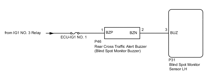
WIRING DIAGRAM
CAUTION / NOTICE / HINT
Note
-
When checking for DTCs, make sure that the blind spot main switch (combination switch assembly) is on.
-
Inspect the fuses for circuits related to this system before performing the following inspection procedure.
PROCEDURE
-
CHECK DTC
-
Clear the DTCs.
Body Electrical > Blind Spot Monitor Slave > Clear DTCs -
Recheck for DTCs and check if the same DTC is output again.
Body Electrical > Blind Spot Monitor Slave > Trouble CodesOK DTC C1ABD and C1ABE are not output. Result Proceed to OK NG
OK 
USE SIMULATION METHOD TO CHECK Click here
NG 
-
-
CHECK HARNESS AND CONNECTOR (REAR CROSS TRAFFIC ALERT BUZZER - BLIND SPOT MONITOR SENSOR LH AND BATTERY)
-
Disconnect the P46 rear cross traffic alert buzzer (blind spot monitor buzzer) connector.
-
Disconnect the P31 blind spot monitor sensor LH connector.
-
Measure the resistance according to the value(s) in the table below.
Standard Resistance Tester Connection Condition Specified Condition P46-2 (BZN) - P31-3 (BUZ) Always Below 1 Ω P46-2 (BZN) - Body ground Always 10 kΩ or higher -
Measure the voltage according to the value(s) in the table below.
Standard Voltage Tester Connection Switch Condition Specified Condition P46-1 (BZP) - Body ground Power switch on (IG) 11 to 14 V P46-1 (BZP) - Body ground Power switch off Below 1 V Result Proceed to OK NG
NG
REPAIR OR REPLACE HARNESS OR CONNECTOR
OK
-
-
CHECK REAR CROSS TRAFFIC ALERT BUZZER (BLIND SPOT MONITOR BUZZER)
-
Replace the rear cross traffic alert buzzer (blind spot monitor buzzer).
-
Clear the DTCs.
Body Electrical > Blind Spot Monitor Slave > Clear DTCs -
Recheck for DTCs and check if the same DTC is output again.
Body Electrical > Blind Spot Monitor Slave > Trouble CodesOK DTC C1ABD and C1ABE are not output. Result Proceed to OK NG
OK
END (REAR CROSS TRAFFIC ALERT BUZZER [BLIND SPOT MONITOR BUZZER] WAS DEFECTIVE)
NG
REPLACE BLIND SPOT MONITOR SENSOR LH Click here
-