LIN COMMUNICATION SYSTEM TERMINALS OF ECU
-
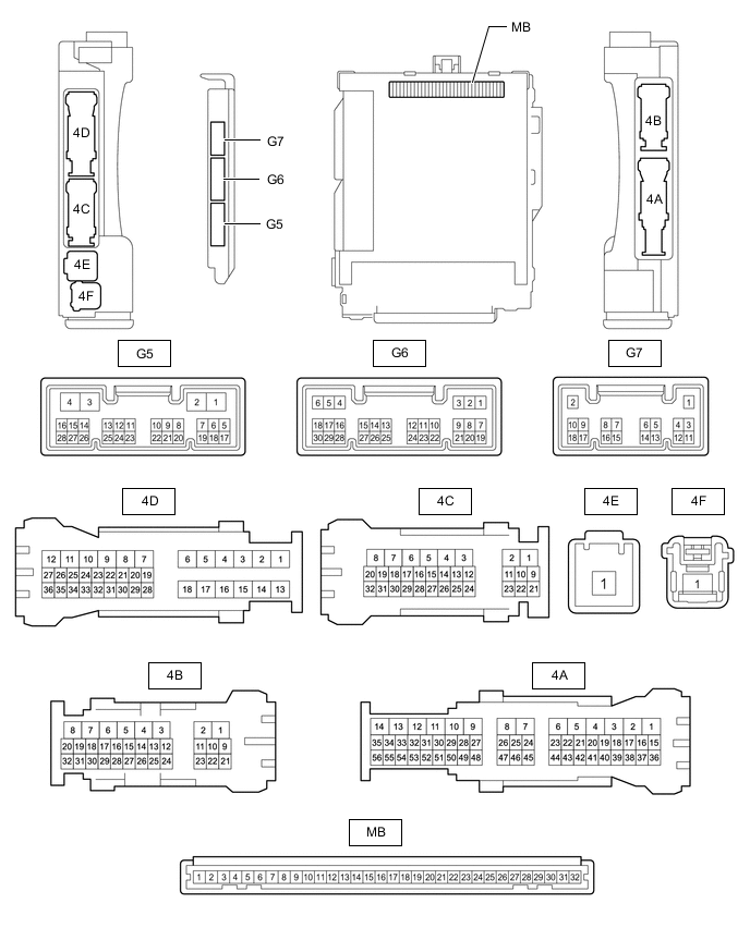
CHECK INSTRUMENT PANEL JUNCTION BLOCK ASSEMBLY AND MAIN BODY ECU (MULTIPLEX NETWORK BODY ECU)
-
Remove the main body ECU (multiplex network body ECU).
-
for LHD: Click here
-
for RHD: Click here
-
-
Measure the voltage and resistance according to the value(s) in the table below.
Tech Tips
Measure the values on the wire harness side with the connectors disconnected.
Tester Connection Wiring Color Terminal Description Condition Specified Condition MB-11 (GND1) - Body ground - Ground Always Below 1 Ω MB-31 (BECU) - Body ground - Auxiliary battery power supply Power switch off 11 to 14 V MB-32 (IG) - Body ground - IG power supply Power switch on (IG) 11 to 14 V MB-32 (IG) - Body ground - IG power supply Power switch off Below 1 V
-
-
CHECK MULTIPLEX NETWORK MASTER SWITCH ASSEMBLY

-
Disconnect the N3 multiplex network master switch assembly connector.
-
Measure the resistance and voltage according to the value(s) in the table below.
Terminal No. (Symbol) Wiring Color Terminal Description Condition Specified Condition N3-11 (B) - Body ground Y - Body ground Auxiliary battery power supply Power switch off 11 to 14 V N3-12 (GND) - Body ground W-B - Body ground Ground Always Below 1 Ω
-
-
CHECK FRONT POWER WINDOW REGULATOR MOTOR ASSEMBLY LH

-
Disconnect the L12 front power window regulator motor assembly LH connector.
-
Measure the resistance and voltage according to the value(s) in the table below.
Terminal No. (Symbol) Wiring Color Terminal Description Condition Specified Condition L12-2 (B) - Body ground SB - Body ground Auxiliary battery power supply Power switch off 11 to 14 V L12-1 (GND) - Body ground W-B - Body ground Ground Always Below 1 Ω
-
-
CHECK FRONT POWER WINDOW REGULATOR MOTOR ASSEMBLY RH

-
Disconnect the L3 front power window regulator motor assembly RH connector.
-
Measure the resistance and voltage according to the value(s) in the table below.
Terminal No. (Symbol) Wiring Color Terminal Description Condition Specified Condition L3-2 (B) - Body ground R - Body ground Auxiliary battery power supply Power switch off 11 to 14 V L3-1 (GND) - Body ground W-B - Body ground Ground Always Below 1 Ω
-
-
CHECK REAR POWER WINDOW REGULATOR MOTOR ASSEMBLY LH

-
Disconnect the M1 rear power window regulator motor assembly LH connector.
-
Measure the resistance and voltage according to the value(s) in the table below.
Terminal No. (Symbol) Wiring Color Terminal Description Condition Specified Condition M1-2 (B) - Body ground G - Body ground Auxiliary battery power supply Power switch off 11 to 14 V M1-1 (GND) - Body ground W-B - Body ground Ground Always Below 1 Ω
-
-
CHECK REAR POWER WINDOW REGULATOR MOTOR ASSEMBLY RH

-
Disconnect the M7 rear power window regulator motor assembly RH connector.
-
Measure the resistance and voltage according to the value(s) in the table below.
Terminal No. (Symbol) Wiring Color Terminal Description Condition Specified Condition M7-2 (B) - Body ground L - Body ground Auxiliary battery power supply Power switch off 11 to 14 V M7-1 (GND) - Body ground W-B - Body ground Ground Always Below 1 Ω
-
-
CHECK CERTIFICATION ECU (SMART KEY ECU ASSEMBLY)
-
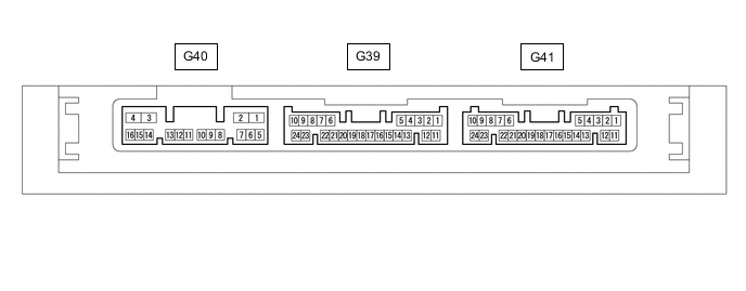
Disconnect the G41 certification ECU (smart key ECU assembly) connector.
-
Measure the resistance and voltage according to the value(s) in the table below.
Terminal No. (Symbol) Wiring Color Terminal Description Condition Specified Condition G41-10 (+B) - Body ground R - Body ground Auxiliary battery power supply Power switch off 11 to 14 V G41-11 (E) - Body ground W-B - Body ground Ground Always Below 1 Ω
-
-
CHECK ID CODE BOX (IMMOBILISER CODE BOX)
-
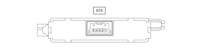
Disconnect the G15 ID code box (immobiliser code ECU) connector.
-
Measure the resistance and voltage according to the value(s) in the table below.
Terminal No. (Symbol) Wiring Color Terminal Description Condition Specified Condition G15-1 (+B) - Body ground R - Body ground Auxiliary battery power supply Power switch off 11 to 14 V G15-5 (GND) - Body ground BR - Body ground Ground Always Below 1 Ω
-
-
CHECK TRANSMISSION CONTROL ECU ASSEMBLY
-
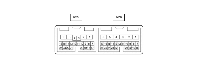
Disconnect the A25 and A26 transmission control ECU assembly connectors.
-
Measure the resistance and voltage according to the value(s) in the table below.
Terminal No. (Symbol) Wiring Color Terminal Description Condition Specified Condition A25-15 (BATT) - Body ground P - Body ground Auxiliary battery power supply Power switch off 11 to 14 V A25-16 (+B) - Body ground G - Body ground IG power supply Power switch on (IG) 11 to 14 V A25-16 (+B) - Body ground G - Body ground IG power supply Power switch off Below 1 V A26-1 (E1) - Body ground W-B - Body ground Ground Always Below 1 Ω
-
-
CHECK RAIN SENSOR

-
Disconnect the W10 rain sensor connector.
-
Measure the resistance and voltage according to the value(s) in the table below.
Terminal No. (Symbol) Wiring Color Terminal Description Condition Specified Condition W10-4 (SIG) - Body ground BE - Body ground IG power supply Power switch on (IG) 11 to 14 V W10-4 (SIG) - Body ground BE - Body ground IG power supply Power switch off Below 1 V W10-2 (ES) - Body ground W-B - Body ground Ground circuit Always Below 1 Ω
-
-
CHECK WINDSHIELD WIPER RELAY ASSEMBLY

-
Disconnect the G32 windshield wiper relay assembly connector.
-
Measure the resistance and voltage according to the value(s) in the table below.
Terminal No. (Symbol) Wiring Color Terminal Description Condition Specified Condition G32-2 (IG) - Body ground Y - Body ground IG power supply Power switch on (IG) 11 to 14 V G32-2 (IG) - Body ground Y - Body ground IG power supply Power switch off Below 1 V G32-12 (E) - Body ground W-B - Body ground Ground Always Below 1 Ω
-
-
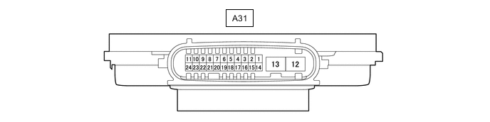
HEADLIGHT LIGHT CONTROL ECU SUB-ASSEMBLY LH
-
Disconnect the A31 headlight light control ECU sub-assembly LH connector.
-
Measure the resistance and voltage according to the value(s) in the table below.
Terminal No. (Symbol) Wiring Color Terminal Description Condition Specified Condition A31-4 (IG) - Body ground LG - Body ground IG power supply Power switch off Below 1 V Power switch on (IG) 11 to 14 V A31-13 (ECUB) - Body ground B - Body ground Auxiliary battery power supply Power switch off Below 1 V Power switch on (IG) 11 to 14 V A31-12 (GND) - Body ground W-B - Body ground Ground Always Below 1 Ω
-
-
HEADLIGHT LIGHT CONTROL ECU SUB-ASSEMBLY RH

-
Disconnect the A30 headlight light control ECU sub-assembly RH connector.
-
Measure the resistance and voltage according to the value(s) in the table below.
Terminal No. (Symbol) Wiring Color Terminal Description Condition Specified Condition A30-4 (IG) - Body ground LG - Body ground IG power supply Power switch off Below 1 V Power switch on (IG) 11 to 14 V A30-13 (ECUB) - Body ground L - Body ground Battery power supply Power switch off Below 1 V Power switch on (IG) 11 to 14 V A30-12 (GND) - Body ground W-B - Body ground Ground Always Below 1 Ω
-