NAVIGATION SYSTEM Reverse Signal Circuit
DESCRIPTION
The radio and display receiver assembly receives a reverse signal from the BACK UP LP relay.
WIRING DIAGRAM
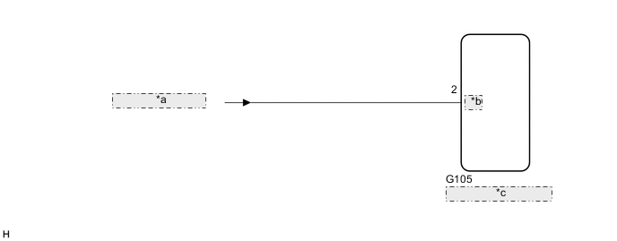
| *a | from BKUP LP Relay |
| *b | REV |
| *c | Radio and Display Receiver Assembly |
PROCEDURE
-
CHECK BACK-UP LIGHT
-
Move the shift lever to R and check if the back-up lights come on.
OK The back-up lights come on. Result Proceed to OK NG
NG 
GO TO LIGHTING SYSTEM Click here
OK 
-
-
CHECK HARNESS AND CONNECTOR (REVERSE SIGNAL)
-
Disconnect the radio and display receiver assembly connector.
-
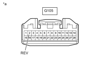
*a Front view of wire harness connector
(to Radio and Display Receiver Assembly)
Measure the voltage according to the value(s) in the table below.
Standard Voltage Tester Connection Condition Specified Condition G105-2 (REV) - Body ground Power switch on (IG)
Shift lever in R
11 to 14 V Power switch on (IG)
Shift lever in any position other than R
Below 1 V Result Proceed to OK NG
OK
PROCEED TO NEXT SUSPECTED AREA SHOWN IN PROBLEM SYMPTOMS TABLE Click here
NG
REPAIR OR REPLACE HARNESS OR CONNECTOR
-