TELEPHONE MICROPHONE REMOVAL
PROCEDURE
-
REMOVE MAP LIGHT ASSEMBLY
-
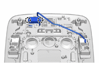
REMOVE TELEPHONE MICROPHONE ASSEMBLY
-
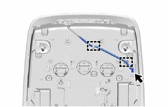
Disconnect the connector.
-
Disengage the guides to separate the wire harness.
-
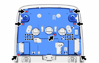
Remove the 7 screws
-
Disengage the guides to remove the cover.
-
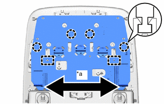

Sliding direction Disengage the guides, and as shown in the illustration, slide to the left and right while disengaging the claws of each switch and knob, and remove the overhead junction block sub-assembly.
-
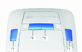
*1 Map Knob *2 Door Knob *3 Room Knob Remove the 4 switch knobs.
-
Disengage the claws to remove the telephone microphone assembly.
-