STEERING COLUMN ASSEMBLY INSTALLATION
CAUTION / NOTICE / HINT
Note
-
Do not replace the spiral cable with sensor sub-assembly with the auxiliary battery connected and the power switch on (IG).
-
Do not rotate the spiral cable with sensor sub-assembly without the steering wheel assembly with the auxiliary battery connected and the power switch on (IG).
-
Ensure that the steering wheel assembly is installed and aligned straight when inspecting the steering sensor.
PROCEDURE
-
INSPECT BUSHING
-
INSTALL NO. 2 STEERING INTERMEDIATE SHAFT ASSEMBLY
-
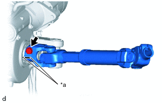
*a Matchmark Align the matchmarks on the No. 2 steering intermediate shaft assembly and steering column assembly to install the No. 2 steering intermediate shaft assembly.
-
Install the bolt.
- Torque:
- 35 N*m { 357 kgf*cm, 26 ft.*lbf }
-
-
ALIGN FRONT WHEELS FACING STRAIGHT AHEAD
-
INSTALL STEERING COLUMN ASSEMBLY
Note
Make sure that the wire harness is not interfering with the steering column assembly.
-
Install the steering column assembly with the bolt and 2 nuts.
- Torque:
- 36 N*m { 367 kgf*cm, 27 ft.*lbf }
-
Engage each wire harness clamp to connect each connector to the steering column assembly.
-

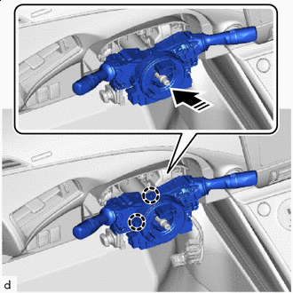
*a Return the Lock Lever *b Push in the Lock Engage the wire harness clamp to the power steering ECU assembly.
-
Connect the connector (A) to the power steering ECU assembly.
Tech Tips
As shown in the illustration, return the lock lever to its original position to connect the connector and securely push in the lock of the lock lever.
-
Connect the connector (B) to the power steering ECU assembly.
-
-
INSTALL NO. 2 AIR DUCT SUB-ASSEMBLY (for LHD)
-
Engage the 2 claws to install the No. 2 air duct sub-assembly.
-
Install the clip.
Note
If the No. 2 air duct sub-assembly is reused, it may fall off or abnormal noise may occur. Therefore, make sure to replace with a new one.
-
-
INSTALL NO. 2 AIR DUCT SUB-ASSEMBLY (for RHD)
-
Engage the 2 claws to install the No. 2 air duct sub-assembly.
Note
If the No. 2 air duct sub-assembly is reused, it may fall off or abnormal noise may occur. Therefore, make sure to replace with a new one.
-
-
INSTALL BRAKE PEDAL SUPPORT ASSEMBLY (for LHD)
-
INSTALL BRAKE PEDAL SUPPORT ASSEMBLY (for RHD)
-
INSTALL MULTIPLEX TILT AND TELESCOPIC ECU
-
INSTALL TURN SIGNAL SWITCH ASSEMBLY WITH SPIRAL CABLE SUB-ASSEMBLY
Note
-
Do not replace the spiral cable with sensor sub-assembly with the auxiliary battery connected and the power switch on (IG).
-
Do not rotate the spiral cable with sensor sub-assembly without the steering wheel assembly with the auxiliary battery connected and the power switch on (IG).
-
Ensure that the steering wheel assembly is installed and aligned straight when inspecting the steering sensor.
-

Install in this Direction Engage the 2 claws to install the turn signal switch assembly with spiral cable sub-assembly to the steering column assembly.
-
Connect each connector to the turn signal switch assembly with spiral cable sub-assembly.
-
-
INSTALL UPPER STEERING COLUMN COVER
-
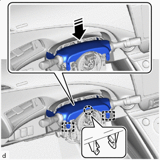
Install in this Direction Engage the claw and 2 guides to install the upper steering column cover.
-
-
INSTALL METER HOOD SPACER
-
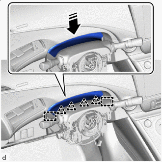
Install in this Direction Engage the 4 clips and 2 guides to install the meter hood spacer to the upper steering column cover.
-
-
INSTALL LOWER STEERING COLUMN COVER
-
Engage the 6 guides and 2 claws to install the lower steering column cover.
-
Install the 3 screws.
-
-
ALIGN FRONT WHEELS FACING STRAIGHT AHEAD
-
INSPECT AND ADJUST SPIRAL CABLE WITH SENSOR SUB-ASSEMBLY
-
INSTALL STEERING WHEEL ASSEMBLY
-
CHECK STEERING WHEEL CENTER POINT
-
INSTALL HORN BUTTON ASSEMBLY
-
PERFORM CALIBRATION OF TORQUE SENSOR ZERO POINT