STEERING COLUMN ASSEMBLY REMOVAL
CAUTION / NOTICE / HINT
The necessary procedures (adjustment, calibration, initialization, or registration) that must be performed after parts are removed, installed, or replaced during the steering column assembly removal/installation are shown below.
| Replacement Part or Procedure | Necessary Procedure | Effects / Inoperative when not Performed | Link |
|---|---|---|---|
| Replacement of steering column assembly | Torque sensor zero point calibration |
|
Note
-
Do not replace the spiral cable with sensor sub-assembly with the auxiliary battery connected and the power switch on (IG).
-
Do not rotate the spiral cable with sensor sub-assembly without the steering wheel assembly with the auxiliary battery connected and the power switch on (IG).
-
Ensure that the steering wheel assembly is installed and aligned straight when inspecting the steering sensor.
PROCEDURE
-
PRECAUTION
-
ALIGN FRONT WHEELS FACING STRAIGHT AHEAD
-
REMOVE HORN BUTTON ASSEMBLY
-
REMOVE STEERING WHEEL ASSEMBLY
-
REMOVE LOWER STEERING COLUMN COVER
-
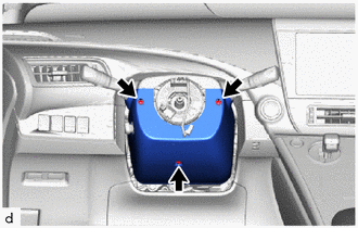
Remove the 3 screws.
-
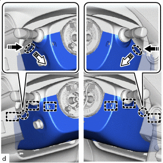

Push Area 
Remove in this Direction (1) 
Remove in this Direction (2) Press in, in the direction shown by the arrow (1) in the illustration, and disengage the 2 claws.
-
Pull out in the direction indicated by the arrow (2) in the illustration, disengage the 6 guides, and remove the lower steering column cover.
-
-
SEPARATE METER HOOD SPACER
-
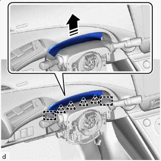
Remove in this Direction Disengage the 4 clips and 2 guides to separate the meter hood spacer from the upper steering column cover.
-
-
REMOVE UPPER STEERING COLUMN COVER
-
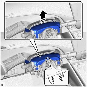
Remove in this Direction Disengage the claw and 2 guides to remove the upper steering column cover.
-
-
REMOVE TURN SIGNAL SWITCH ASSEMBLY WITH SPIRAL CABLE SUB-ASSEMBLY
Note
-
Do not replace the spiral cable with sensor sub-assembly with the auxiliary battery connected and the power switch on (IG).
-
Do not rotate the spiral cable with sensor sub-assembly without the steering wheel assembly with the auxiliary battery connected and the power switch on (IG).
-
Ensure that the steering wheel assembly is installed and aligned straight when inspecting the steering sensor.
-
Disconnect each connector from the turn signal switch assembly with spiral cable sub-assembly.
-
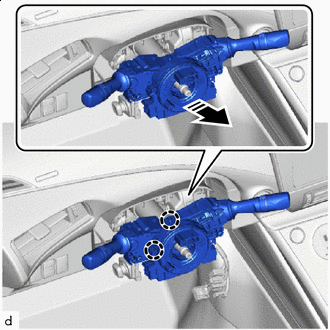
Remove in this Direction Disengage the 2 claws to remove the turn signal switch assembly with spiral cable sub-assembly from the steering column assembly.
-
-
REMOVE MULTIPLEX TILT AND TELESCOPIC ECU
-
REMOVE BRAKE PEDAL SUPPORT ASSEMBLY (for LHD)
-
REMOVE BRAKE PEDAL SUPPORT ASSEMBLY (for RHD)
-
REMOVE NO. 2 AIR DUCT SUB-ASSEMBLY (for LHD)
-
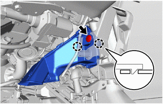
Remove the clip.
-
Disengage the 2 claws to remove the No. 2 air duct sub-assembly.
Note
If any of the claws of the No. 2 air duct sub-assembly have been cracked or deformed during removal, make sure to replace the air duct with a new one. Failure to do so may cause the No. 2 air duct sub-assembly to fall off or noise to occur.
-
-
REMOVE NO. 2 AIR DUCT SUB-ASSEMBLY (for RHD)
-
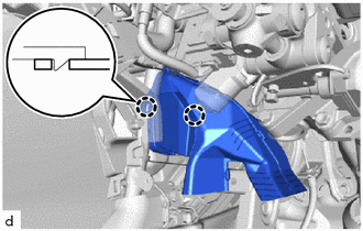
Disengage the 2 claws to remove the No. 2 air duct sub-assembly.
Note
If any of the claws of the No. 2 air duct sub-assembly have been cracked or deformed during removal, make sure to replace the air duct with a new one. Failure to do so may cause the No. 2 air duct sub-assembly to fall off or noise to occur.
-
-
REMOVE STEERING COLUMN ASSEMBLY
-
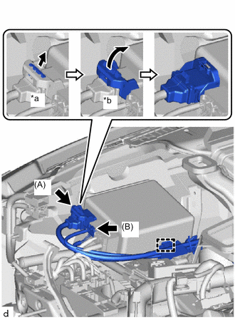
*a Pull Out the Lock *b Lift Up the Lock Lever Disconnect the connector (A) from the power steering ECU assembly.
Tech Tips
As shown in the illustration, pull out the lock of the lock lever and turn the lock lever to disconnect the connector.
-
Disconnect the connector (B) from the power steering ECU assembly.
-
Disengage the wire harness clamp from the power steering ECU assembly.
-
Disconnect the connectors to disengage the wire harness clamps from the steering column assembly.
-
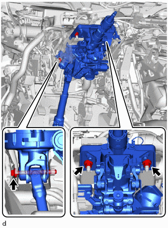
Remove the bolt, 2 nuts and steering column assembly.
-
-
REMOVE NO. 2 STEERING INTERMEDIATE SHAFT ASSEMBLY
-
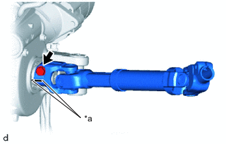
*a Matchmark Put matchmarks on the No. 2 steering intermediate shaft assembly and steering column assembly.
-
Remove the bolt and No. 2 steering intermediate shaft assembly from the steering column assembly.
-