POWER STEERING SYSTEM, Diagnostic DTC:C1522/24, C1523/24, C1524/24, C1555/25
| DTC Code | DTC Name |
|---|---|
| C1522/24 | Power Supply Sensor |
| C1523/24 | Current Deviation Excessive |
| C1524/24 | Motor Terminal Voltage Malfunction |
| C1555/25 | Motor Relay Welding Failure |
DESCRIPTION
The power steering ECU supplies current to the power steering motor through the motor circuit.
| DTC No. | Detection Item | DTC Detection Condition | Trouble Area | Warning Indicate | Return-to-normal Condition | Note |
|---|---|---|---|---|---|---|
| C1522/24 | Power Supply Sensor | Motor current sensor malfunction | Power steering ECU assembly | On | Power switch on (IG) again | - |
| C1523/24 | Current Deviation Excessive | Excessively large current deviation | Power steering ECU assembly | On | Power switch on (IG) again | - |
| C1524/24 | Motor Terminal Voltage Malfunction | Short (or open) in motor circuit or abnormal voltage or current in motor circuit | Power steering ECU assembly | On | Power switch on (IG) again | - |
| C1555/25 | Motor Relay Welding Failure | Motor relay circuit malfunction | Power steering ECU assembly | On | Power switch on (IG) again | - |
WIRING DIAGRAM
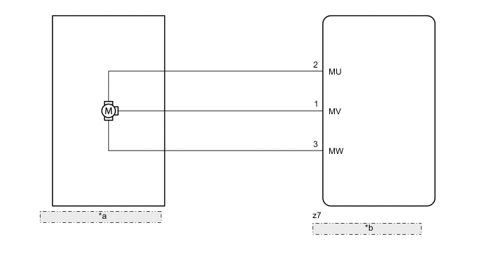
| *a | Power Steering Column Assembly |
| *b | Power Steering ECU Assembly |
CAUTION / NOTICE / HINT
Note
-
If the steering column assembly has been replaced, perform rotation angle sensor value initialization and torque sensor zero point calibration.
-
If the power steering ECU assembly has been replaced, perform assist map writing, rotation angle sensor value initialization and torque sensor zero point calibration.
PROCEDURE
-
READ VALUE USING GTS (MOTOR VOLTAGE)
-
Turn the power switch off.
-
Connect the GTS to the DLC3.
-
Turn the power switch on (READY).
-
Turn the GTS on.
-
Enter the following menus: Chassis / EMPS / Data List.
-
Select the item "Motor Terminal Volt(U)", "Motor Terminal Volt(V)" and "Motor Terminal Volt(W)" in the Data List and read the value displayed on the GTS.
Chassis > EMPS > Data ListTester Display Measurement Item Range Normal Condition Diagnostic Note Motor Terminal Volt(U) Motor terminal voltage (A phase) Min.: 0.000 V
Max.: 98.000 V
Value changes within 4 to 35 V range Power switch on (READY) and steering wheel is being turned Motor Terminal Volt(V) Motor terminal voltage (B phase) Min.: 0.000 V
Max.: 98.000 V
Value changes within 4 to 35 V range Power switch on (READY) and steering wheel is being turned Motor Terminal Volt(W) Motor terminal voltage (C phase) Min.: 0.000 V
Max.: 98.000 V
Value changes within 4 to 35 V range Power switch on (READY) and steering wheel is being turned
Chassis > EMPS > Data ListTester Display Motor Terminal Volt(U) Motor Terminal Volt(V) Motor Terminal Volt(W) Result Result Proceed to During steering operation, value changes within 4 to 35 V range A During steering operation, voltage is not generated B
A 
REPLACE POWER STEERING ECU ASSEMBLY Click here
B
REPLACE STEERING COLUMN ASSEMBLY Click here
-