POWER STEERING SYSTEM, Diagnostic DTC:C1528/12
| DTC Code | DTC Name |
|---|---|
| C1528/12 | Motor Rotation Angle Sensor Malfunction |
DESCRIPTION
The motor rotation angle sensor detects the motor rotation angle and sends this information to the power steering ECU.
| DTC No. | Detection Item | DTC Detection Condition | Trouble Area | Warning Indicate | Return-to-normal Condition | Note |
|---|---|---|---|---|---|---|
| C1528/12 | Motor Rotation Angle Sensor Malfunction | Motor rotation angle sensor malfunction | Power steering ECU assembly | On | Power switch on (IG) again | - |
WIRING DIAGRAM
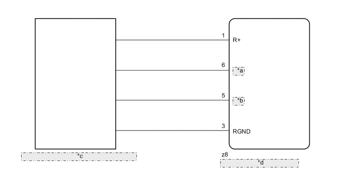
| *a | RSIN |
| *b | RCOS |
| *c | Motor Rotation Angle Sensor (built into Power Steering Column) |
| *d | Power Steering ECU Assembly |
PROCEDURE
-
CHECK CONNECTOR CONNECTION CONDITION
-
Check the connection condition of the torque sensor connector.
OK Torque sensor connector is securely connected to the power steering ECU assembly. Result Proceed to OK NG
NG 
CONNECT CONNECTOR
OK 
-
-
READ VALUE USING GTS (MOTOR ROTATION ANGLE)
-
Turn the power switch off.
-
Connect the GTS to the DLC3.
-
Turn the power switch on (IG).
-
Turn the GTS on.
-
Enter the following menus: Chassis / EMPS / Data List.
-
Select the item "Motor Rotation Angle" in the Data List and read the value displayed on the GTS.
Chassis > EMPS > Data ListTester Display Measurement Item Range Normal Condition Diagnostic Note Motor Rotation Angle Motor rotation angle Min.: 0.000 deg
Max.: 1441.770 deg
During steering operation, motor rotation angle value changes from 0 to 360° Power switch on (READY) and power steering is in operation
Chassis > EMPS > Data ListTester Display Motor Rotation Angle OK During steering operation, motor rotation anglevalue changes from 0 to 360°. Result Proceed to OK NG
OK
REPLACE POWER STEERING ECU ASSEMBLY Click here
NG
-
-
CHECK HARNESS AND CONNECTOR
-
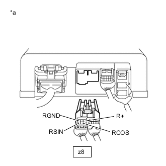
*a Front view of wire harness connector
(to Motor Rotation Angle Sensor)
Disconnect the connector from the motor rotation angle sensor.
-
Measure the resistance according to the value(s) in the table below.
Standard Resistance Tester Connection Condition Specified Condition z8-1(R+) -z8-3(RGND) Always 27.6 to 41.4 Ω z8-6(RSIN) -z8-3(RGND) Always 75.2 to 112.8 Ω z8-5(RCOS) -z8-3(RGND) Always 73.2 to 110.8 Ω Result Proceed to OK NG
OK
REPLACE POWER STEERING ECU ASSEMBLY Click here
NG
REPLACE STEERING COLUMN ASSEMBLY Click here
-