PARKING BRAKE ASSEMBLY REASSEMBLY

CAUTION / NOTICE / HINT
Note
-
When the brake pedal is first depressed after replacing the brake pads or pushing back the disc brake piston, DTC C1214 may be output. As there is no malfunction, clear the DTCs.
-
While the auxiliary battery is connected, even if the power switch is off, the brake control system activates when the brake pedal is depressed or the door courtesy switch is turned on. Therefore, even if only brake pads are to be removed and installed, be sure to perform the Disable Brake Control procedure and disconnect the cable from the negative (-) terminal of the auxiliary battery before beginning work.
Tech Tips
-
The following procedure is for the LH side.
-
Use the same procedure for the RH and LH sides.
PROCEDURE
-
INSTALL PARKING BRAKE SHOE HOLD DOWN SPRING PIN (for Rear Side)
-
Clean the installation surface of the parking brake plate sub-assembly.
-
Install the parking brake shoe hold down spring pin of the rear side to the parking brake plate sub-assembly.
-
Temporarily install the parking brake plate sub-assembly to the rear axle beam assembly.
Note
Make sure that the No. 3 parking brake cable assembly is not twisted during reassembly.
Tech Tips
The parking brake plate sub-assembly will be fully installed after installing the rear axle hub and bearing assembly.
-
Install the rear axle hub and bearing assembly.
-
Fully tighten the installation nut of the parking brake plate sub-assembly.
- Torque:
- 140 N*m { 1428 kgf*cm, 103 ft.*lbf }
-
-
APPLY HIGH TEMPERATURE GREASE
-
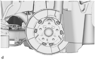

High Temperature Grease Apply high temperature grease to the areas of the parking brake plate sub-assembly which make contact with the shoes as shown in the illustration.
-
-
INSTALL PARKING BRAKE SHOE HOLD DOWN SPRING PIN (for Front Side)
-
Install the parking brake shoe hold down spring pin of the front side to the backing plate.
-
-
INSTALL PARKING BRAKE SHOE LEVER
-
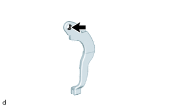
Apply high temperature grease to the areas of the parking brake shoe lever which make contact with the No. 2 parking brake shoe assembly.
-
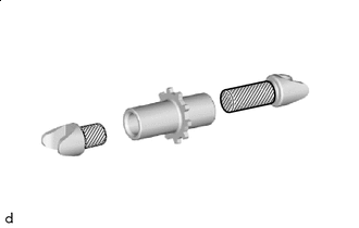
Temporarily install the parking brake shoe lever to the No. 2 parking brake shoe assembly with a new parking brake shoe type C washer.
-
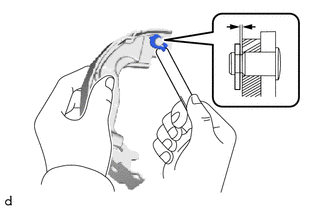
Using a feeler gauge, measure the clearance between the No. 1 parking brake shoe assembly and parking brake shoe lever.
Standard Clearance Less than 0.35 mm (0.0138 in.) -
If the clearance is not as specified, replace the parking brake shoe shim with one of the correct size.
Parking Brake Shoe Shim Part No. Shim Thickness 90564-09184 0.3 mm (0.0118 in.) 90564-09185 0.6 mm (0.0236 in.) 90564-09186 0.9 mm (0.0354 in.) -
Select a parking brake shoe shim and install it and the parking brake shoe type C washer.
-
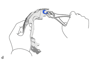
Using a pair of pliers, squeeze together the ends of the parking brake shoe type C washer.
-
Check that the parking brake shoe lever moves smoothly.
-
-
CONNECT PARKING BRAKE SHOE LEVER
-
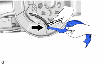
Using needle-nose pliers, connect the parking brake shoe lever to the No. 3 parking brake cable assembly.
-
-
INSTALL NO. 2 PARKING BRAKE SHOE RETURN TENSION SPRING
-
Install the No. 2 parking brake shoe return tension spring to the No. 2 parking brake shoe assembly.
-
-
INSTALL NO. 1 PARKING BRAKE SHOE ASSEMBLY
-
Install the No. 1 parking brake shoe assembly to the No. 2 parking brake shoe return tension spring.
-
-
INSTALL PARKING BRAKE SHOE ADJUSTING SCREW SET
-
High Temperature Grease Apply high temperature grease to the parking brake shoe adjusting screw set as shown in the illustration.
-
Install the parking brake shoe adjusting screw set to the No. 1 parking brake shoe assembly and No. 2 parking brake shoe assembly.
-
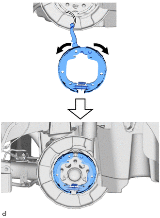
Expand the No. 1 parking brake shoe assembly and No. 2 parking brake shoe assembly outward and fit them to the parking brake plate sub-assembly.
Note
Make sure that the parking brake shoe lever does not separate from the No. 2 parking brake shoe assembly.
-
-
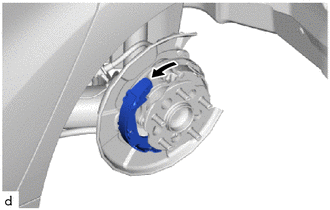
INSTALL BRAKE SHOE HOLD DOWN SPRING (for Rear Side)
-
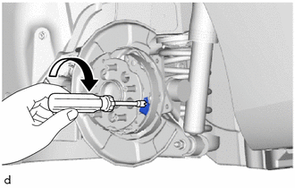
Using SST, rotate the parking brake shoe hold down spring pin, and install the brake shoe hold down spring.
- SST
- 09718-00011
-
-
INSTALL PARKING BRAKE SHOE STRUT
-
Expand the No. 1 parking brake shoe assembly outward.
-
Install the parking brake shoe strut.
-
Install the No. 1 parking brake shoe assembly.
-
-
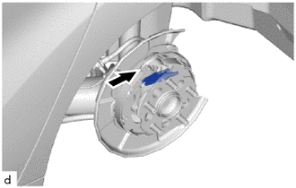
INSTALL BRAKE SHOE HOLD DOWN SPRING (for Front Side)
-
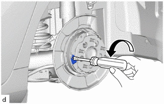
Using SST, rotate the parking brake shoe hold down spring pin, and install the brake shoe hold down spring.
- SST
- 09718-00011
-
-
INSTALL NO. 1 PARKING BRAKE SHOE RETURN TENSION SPRING
-
Install the No. 1 parking brake shoe return tension spring.
-
-
INSTALL NO. 3 PARKING BRAKE SHOE RETURN TENSION SPRING
-
Install the No. 3 parking brake shoe return tension spring.
-
-
CHECK PARKING BRAKE INSTALLATION
-
Check that each part is installed properly.
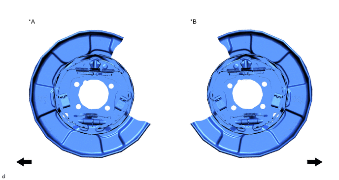
*A for LH Side *B for RH Side 
Front of the Vehicle - -
-
-
INSTALL REAR DISC
-
INSTALL PARKING BRAKE SHOE ADJUSTING HOLE PLUG
-
INSTALL REAR DISC BRAKE CALIPER ASSEMBLY
-
INSTALL REAR WHEEL
-
ADJUST PARKING BRAKE PEDAL TRAVEL
-
CONNECT CABLE TO NEGATIVE AUXILIARY BATTERY TERMINAL
-
Connect cable to negative auxiliary battery terminal.
-
Install the luggage trim service hole cover.
-
Connect the reservoir level switch connector.
-
Turn the power switch on (IG).
-
Fully depress the parking brake pedal to engage the parking brake.
-
Clear the DTCs.
-