FRONT BRAKE INSPECTION
PROCEDURE
-
INSPECT BRAKE CYLINDER AND PISTON
-
Check the disc brake cylinder bore and front disc brake piston for rust and scoring. If necessary, replace the disc brake cylinder assembly or front disc brake piston.
-
-
INSPECT PAD LINING THICKNESS
-
Using a ruler, measure the front disc brake pad lining thickness.
Standard Thickness 12.0 mm (0.472 in.) Minimum Thickness 1.0 mm (0.0394 in.) Tech Tips
Be sure to check the front disc thickness when replacing the front disc brake pads with new ones.
If a front disc brake pad lining thickness is less than the minimum thickness, replace the front disc brake pads.
-
-
INSPECT FRONT DISC BRAKE PAD SUPPORT PLATE
-
Clean the front disc brake pad support plate with brake cleaner, and check that the front disc brake pad support plate has no deformation, cracks, rust, or difficult to remove foreign matter.
-
When installing the front disc brake pad support plate, use brake cleaner to clean the surface of the front disc brake cylinder mounting that contacts the front disc brake pad support plate, and with the front disc brake pad support plate installed to the front disc brake cylinder mounting, check that there is no looseness or deformation.
-
When installing the front disc brake pad, check that the front disc brake pad support plate has spring force, and that the front disc brake pad does not easily fall off.
-
-
INSPECT DISC THICKNESS
-
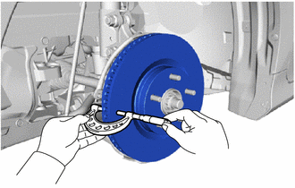
Using a micrometer, measure the front disc thickness.
Standard Thickness 28.0 mm (1.10 in.) Minimum Thickness 25.0 mm (0.984 in.) If the front disc thickness is less than the minimum thickness, replace the front disc.
-
-
INSPECT DISC RUNOUT
-
Inspect the front axle hub bearing looseness and front axle hub runout.
-
Align the matchmarks on the front disc and front axle hub sub-assembly, and install the front disc with the 5 hub nuts.
- Torque:
- 103 N*m { 1050 kgf*cm, 76 ft.*lbf }
-
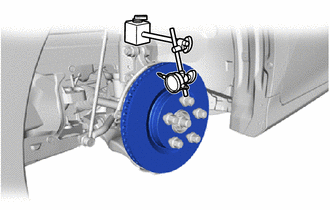
Using a dial indicator, measure the disc runout 10 mm (0.394 in.) from the outer edge of the front disc.
Maximum Disc Runout 0.05 mm (0.00197 in.) Note
-
Do not place the magnetic portion of the dial indicator near the front speed sensor.
-
If the runout exceeds the specified limit, adjust the phase of the front disc and the front axle hub to minimize the runout, and reinstall them. If the runout still exceeds the specified limit, grind the front disc. If grinding the front disc results in a front disc thickness that is less than the specified minimum, replace the front disc with a new one.
-
-
Remove the 5 hub nuts and front disc.
-