POWER STEERING SYSTEM TERMINALS OF ECU
-
CHECK POWER STEERING ECU ASSEMBLY
*a Component with harness connected
(Power Steering ECU Assembly)
- - Tech Tips
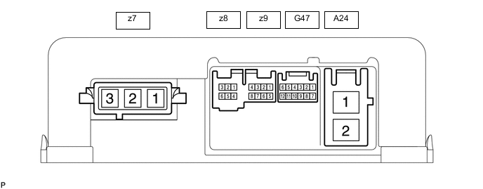
As connector z7 uses a lock lever, each terminal cannot be checked while the connector is still connected to the power steering ECU.
Terminal No. (Symbol) Wiring Color Terminal Description z7-1 (MV) W V phase motor output z7-2 (MU) B U phase motor output z7-3 (MW) R W phase motor output
-
Measure the voltage and resistance according to the value(s) in the table below.
Note
When the power steering warning light (red) is illuminated due to a malfunction, the fail-safe function may cause the voltage of the power steering ECU assembly terminals to become 0 V.
Terminal No. (Symbol) Wiring Color Terminal Description Condition Specified Condition z8-1(R+) - Body ground R - Body ground Rotation angle sensor excitation output signal Power switch on (READY), Steering wheel turned 0.68 to 4.42 V z8-3(RGND) - Body ground B - Body ground Rotation angle sensor excitation circuit GND Always Below 1 Ω z8-5(RCOS) - Body ground L - Body ground Rotation angle sensor COS aspect output signal Power switch on (READY), Steering wheel turned 0.68 to 4.42 V z8-6(RSIN) - Body ground Y - Body ground Rotation angle sensor SIN aspect output signal Power switch on (READY), Steering wheel turned 0.68 to 4.42 V z9-5(TRQ1) - Body ground W - Body ground Torque sensor 1 signal Power switch on (READY), steering wheel not being turned (without load) 2.3 to 2.7 V Power switch on (READY), steering wheel being turned to the right with vehicle stopped 2.5 to 3.8 V Power switch on (READY), steering wheel being turned to the left with vehicle stopped 1.2 to 2.5 V z9-6(TRQV) - z9-8(TRQG) R - B Torque sensor ground Always Below 1 Ω z9-7(TRQ2) - Body ground Y - Body ground Torque sensor 2 signal Power switch on (READY), steering wheel not being turned (without load) 2.3 to 2.7 V Power switch on (READY), steering wheel being turned to the left with vehicle stopped 1.2 to 2.5 V Power switch on (READY), steering wheel being turned to the right with vehicle stopped 2.5 to 3.8 V z9-8(TRQG) - Body ground B - Body ground Torque sensor ground Always Below 1 Ω G47-1(CANH) - G47-7(CANL) R - W CAN communication line Power switch off 54 to 69 Ω G47-6(IG) - Body ground LG - Body ground IG power source Power switch on (IG) 9 to 16 V A24-1(PIG) - Body ground B - Body ground Power source Power switch off 9 to 16 V A24-2(PGND) - Body ground W-B - Body ground Power ground Always Below 1 Ω
-