ELECTRONICALLY CONTROLLED BRAKE SYSTEM, Diagnostic DTC:C1311/11, C1312/12
| DTC Code | DTC Name |
|---|---|
| C1311/11 | Open in Main Relay 1 Circuit |
| C1312/12 | Short in Main Relay 1 Circuit |
DESCRIPTION
The ABS main relay supplies power to the changeover solenoid and the linear solenoid.
The ABS main relay remains on for approximately 2 minutes after the power switch is turned off and the input of brake pedal operation signals stops, and supplies power to the system to keep it ready to operate.
| DTC No. | Detection Item | INF Code | DTC Detection Condition | Trouble Area | Note |
|---|---|---|---|---|---|
| C1311/11 | Open in Main Relay 1 Circuit | 1 | Either of the following is detected:
|
|
Electronically controlled brake system DTC |
| C1312/12 | Short in Main Relay 1 Circuit | 2 | The ABS main relay contact is turned ON (BS terminal voltage 3.5 V or more) for 4.5 seconds or more when the ABS main relay OFF is requested from the ECU. |
|
Electronically controlled brake system DTC |
CAUTION / NOTICE / HINT
Note
-
When replacing the skid control ECU (brake booster with master cylinder assembly), perform initialization and calibration of the linear solenoid valve.
-
Inspect the fuses for circuits related to this system before performing the following procedure.
PROCEDURE
-
PERFORM ACTIVE TEST USING GTS (ECB MAIN RELAY)
-
Connect the GTS to the DLC3.
-
Turn the power switch on (IG).
-
Select the Active Test on the GTS.
Chassis > ABS/VSC/TRC > Active TestTester Display Measurement Item Control Range Diagnostic Note ECB Main Relay ABS main relay Relay ON/OFF ECB: Electronically Controlled Brake System
Chassis > ABS/VSC/TRC > Active TestTester Display ECB Main Relay -
Select the Data List on the GTS.
Chassis > ABS/VSC/TRC > Data ListTester Display Measurement Item Range Normal Condition Diagnostic Note ECB Main Relay ABS main relay ON or OFF ON: Relay on
OFF: Relay off
ECB: Electronically Controlled Brake System
Chassis > ABS/VSC/TRC > Data ListTester Display ECB Main Relay -
Check that the condition of the ABS main relay observed on the GTS changes according to the GTS operation.
Result Result Proceed to ABS main relay in the Data List turns ON/OFF using the Active Test. A ABS main relay in the Data List does not change using the Active Test. B
B 
CHECK HARNESS AND CONNECTOR (BI TERMINAL) Click here
A 
-
-
CHECK HARNESS AND CONNECTOR (BS TERMINAL)
-

*a Front view of wire harness connector
(to Skid Control ECU (Brake Booster with Master Cylinder Assembly))
Turn the power switch off.
-
Make sure that there is no looseness at the locking part and the connecting part of the connector.
-
Disconnect the A63 skid control ECU (brake booster with master cylinder assembly) connector.
-
Measure the voltage according to the value(s) in the table below.
Standard Voltage Tester Connection Condition Specified Condition A63-15 (BS) - Body ground Always 11 to 14 V Result Proceed to OK NG
NG 
REPAIR OR REPLACE HARNESS OR CONNECTOR (BS CIRCUIT)
OK
-
-
RECONFIRM DTC
-
Reconnect the A63 skid control ECU (brake booster with master cylinder assembly) connector.
-
Clear the DTCs.
Chassis > ABS/VSC/TRC > Clear DTCs -
Turn the power switch off.
-
Turn the power switch on (IG).
-
Check if the same DTC is output.
Chassis > ABS/VSC/TRC > Trouble CodesResult Result Proceed to DTCs C1311/11 and C1312/12 are not output. A DTCs C1311/11 and/or C1312/12 are output (for RHD). B DTCs C1311/11 and/or C1312/12 are output (for LHD). C
A
USE SIMULATION METHOD TO CHECK Click here
B
REPLACE BRAKE BOOSTER WITH MASTER CYLINDER ASSEMBLY Click here
C
REPLACE BRAKE BOOSTER WITH MASTER CYLINDER ASSEMBLY Click here
-
-
CHECK HARNESS AND CONNECTOR (BI TERMINAL)
-
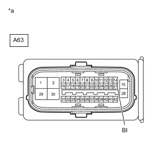
*a Front view of wire harness connector
(to Skid Control ECU (Brake Booster with Master Cylinder Assembly))
Turn the power switch off.
-
Make sure that there is no looseness at the locking part and the connecting part of the connector.
-
Disconnect the A63 skid control ECU (brake booster with master cylinder assembly) connector.
-
Measure the voltage according to the value(s) in the table below.
Standard Voltage Tester Connection Condition Specified Condition A63-14 (BI) - Body ground Always 11 to 14 V Result Proceed to OK NG
NG
REPAIR OR REPLACE HARNESS OR CONNECTOR (BI CIRCUIT)
OK
-
-
CHECK HARNESS AND CONNECTOR (BS TERMINAL)
-
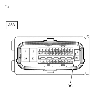
*a Front view of wire harness connector
(to Skid Control ECU (Brake Booster with Master Cylinder Assembly))
Measure the voltage according to the value(s) in the table below.
Standard Voltage Tester Connection Condition Specified Condition A63-15 (BS) - Body ground Always 11 to 14 V Result Result Proceed to OK (for RHD) A OK (for LHD) B NG C
A
REPLACE BRAKE BOOSTER WITH MASTER CYLINDER ASSEMBLY Click here
B
REPLACE BRAKE BOOSTER WITH MASTER CYLINDER ASSEMBLY Click here
C
REPAIR OR REPLACE HARNESS OR CONNECTOR (BS CIRCUIT)
-