BRAKE PEDAL(for LHD) REMOVAL
CAUTION / NOTICE / HINT
The necessary procedures (adjustment, calibration, initialization, or registration) that must be performed after parts are removed, installed, or replaced during the brake pedal support assembly removal/installation are shown below.
CAUTION / NOTICE / HINT
| Replacement Part or Procedure | Necessary Procedure | Effects/Inoperative when not Performed | Link |
|---|---|---|---|
|
|
|
Note
While the auxiliary battery is connected, even if the power switch is off, the brake control system activates when the brake pedal is depressed or any door courtesy switch is turned on. Therefore, when servicing brake system components, do not depress the brake pedal or open/close the doors while the auxiliary battery is connected.
PROCEDURE
-
PLACE FRONT WHEELS FACING STRAIGHT AHEAD
-
REMOVE UPPER INSTRUMENT PANEL SUB-ASSEMBLY
-
REMOVE STOP LIGHT SWITCH ASSEMBLY
-
REMOVE STOP LIGHT SWITCH MOUNTING ADJUSTER
-
REMOVE BRAKE PEDAL STROKE SENSOR ASSEMBLY
-
REMOVE COLUMN HOLE COVER SILENCER SHEET
-
Turn back the floor carpet.
-
Remove the 2 clips and column hole cover silencer sheet.
-
-
SEPARATE NO. 2 STEERING INTERMEDIATE SHAFT ASSEMBLY
-
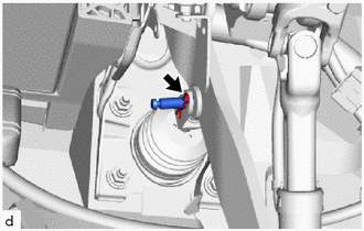
*a Matchmark Place matchmarks on the steering intermediate shaft and No. 2 steering intermediate shaft assembly.
-
Remove the bolt.
-
Disconnect the No. 2 steering intermediate shaft assembly from the steering intermediate shaft.
-
-
REMOVE BRAKE PEDAL RETURN SPRING
-
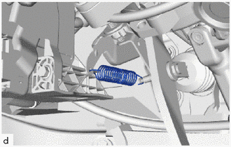
Remove the brake pedal return spring from the brake pedal support assembly and push rod pin.
-
-
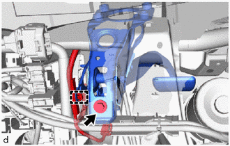
REMOVE PUSH ROD PIN
-
Remove the clip and push rod pin.
-
-
REMOVE BRAKE PEDAL SUPPORT ASSEMBLY
-
Disengage the clamp to separate the wire harness from the brake pedal support assembly.
-
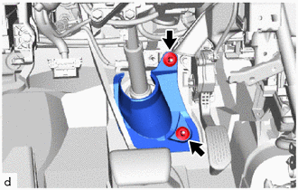
Remove the bolt to separate the brake pedal support assembly from the instrument panel reinforcement assembly.
-
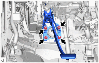
Remove the 4 nuts and brake pedal support assembly.
-
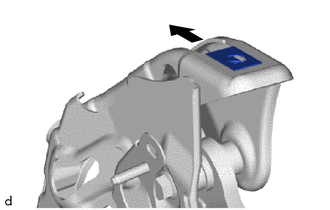
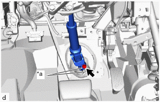
Remove the nut from the brake pedal support assembly as shown in the illustration.
-
-
REMOVE BRAKE PEDAL PAD
-
Remove the brake pedal pad from the brake pedal support assembly.
-