REAR SHOCK ABSORBER REMOVAL

CAUTION / NOTICE / HINT
The necessary procedures (adjustment, calibration, initialization, or registration) that must be performed after parts are removed, installed, or replaced during the rear shock absorber assembly removal/installation are shown below.
| Replacement Part or Procedure | Necessary Procedure | Effects/Inoperative when not Performed | Link |
|---|---|---|---|
| Rear height control sensor sub-assembly |
|
Automatic headlight beam level control system | |
| Rear shock absorber assembly |
|
VSC malfunctioning | |
| Adjust lane departure warning camera | Lane departure alert system does not operate correctly |
Tech Tips
-
Use the same procedure for the RH side and LH side.
-
The following procedure is for the LH side.
PROCEDURE
-
REMOVE LUGGAGE COMPARTMENT FLOOR MAT
-
REMOVE NO. 1 LUGGAGE COMPARTMENT LIGHT ASSEMBLY
-
REMOVE NO. 2 LUGGAGE COMPARTMENT TRIM HOOK
-
REMOVE FRONT LUGGAGE COMPARTMENT TRIM COVER
-
REMOVE REAR FLOOR FINISH PLATE
-
REMOVE ROPE HOOK
-
REMOVE LUGGAGE COMPARTMENT TRIM COVER ASSEMBLY LH
-
REMOVE LUGGAGE COMPARTMENT TRIM COVER ASSEMBLY RH
-
REMOVE NO. 3 BODY MOUNTING BRACKET SUB-ASSEMBLY LH
-
REMOVE NO. 3 BODY MOUNTING BRACKET SUB-ASSEMBLY RH
-
REMOVE REAR WHEEL
-
DISCONNECT REAR HEIGHT CONTROL SENSOR SUB-ASSEMBLY
-
REMOVE REAR SHOCK ABSORBER CUSHION RETAINER
-
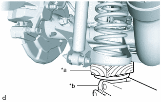
*a Wooden Block *b Jack Using a jack and wooden block, support the rear axle beam assembly.
Note
-
When jacking up the rear axle beam assembly, be sure to jack it up slowly.
-
Make sure to perform this operation with the vehicle kept as low as possible.
-
Keep supporting the rear axle beam assembly with a jack until the installation of the rear shock absorber assembly has been completed.
-
-
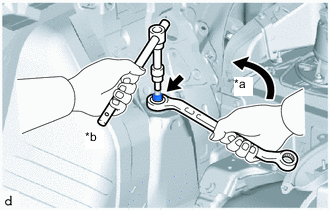
*a Turn *b Hold Using a 6 mm hexagon socket wrench, secure the rear shock absorber assembly rod and remove the rear support to rear shock absorber nut using a wrench.
Note
Securely insert the 6 mm hexagon socket wrench into the rear shock absorber assembly rod to prevent damage to the rear shock absorber assembly when removing the rear support to rear shock absorber nut.
-
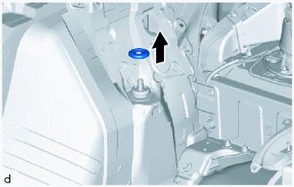
Remove the rear shock absorber cushion retainer.
-
-
REMOVE REAR SUSPENSION SUPPORT
-
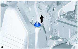
Remove the rear suspension support.
-
-
REMOVE REAR SHOCK ABSORBER ASSEMBLY
-
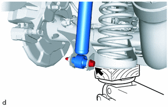
Remove the bolt, nut and rear shock absorber assembly with rear No. 1 spring bumper from the vehicle.
Note
Because the nut has its own stopper, do not turn the nut. Loosen the bolt with the nut secured.
-
-
REMOVE REAR NO. 1 SPRING BUMPER
-
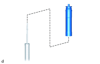
Remove the rear No. 1 spring bumper from the rear shock absorber assembly.
-