FRONT SUSPENSION MEMBER INSTALLATION

PROCEDURE
-
INSTALL FRONT SUSPENSION MEMBER BODY MOUNTING REAR CUSHION
-
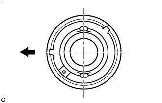

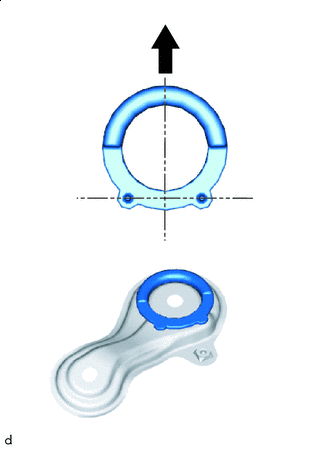
Front of the Vehicle Align a new front suspension member body mounting rear cushion as shown in the illustration and set it to the front suspension crossmember sub-assembly.
-
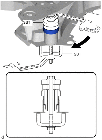
*a Hold *b Turn Using SST, press the front suspension member body mounting rear cushion into the front suspension crossmember sub-assembly.
- SST
- 09710-28031 ( 09711-02010, 09711-02030, 09711-02040, 94622-51200 )
- 09950-60010 ( 09951-00600, 09951-00610 )
Tech Tips
Apply grease to the threads of SST.
-
-
INSTALL FRONT UPPER BODY MOUNTING CUSHION
-
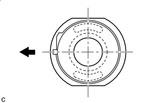
Front of the Vehicle Align a new front upper body mounting cushion as shown in the illustration and set it to the front suspension crossmember sub-assembly.
-
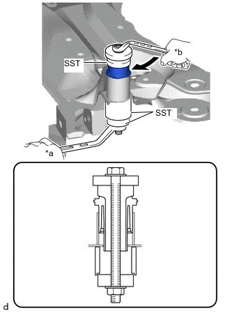
*a Hold *b Turn Using SST, press the front upper body mounting cushion into the front suspension crossmember sub-assembly.
- SST
- 09710-28031 ( 09711-02030, 09711-02040, 94622-51200 )
- 09710-30021 ( 09710-03141 )
- 09950-60010 ( 09951-00440, 09951-00600 )
Tech Tips
Apply grease to the threads of SST.
-
-
INSTALL FRONT SUSPENSION MEMBER BODY MOUNTING REAR STOPPER
-
Front of the Vehicle Install the 2 front suspension member body mounting rear stoppers to the front suspension member rear brace LH and front suspension member rear brace RH.
-
-
INSTALL FRONT SUSPENSION MEMBER BODY MOUNTING FRONT STOPPER
-
Install the 2 front suspension member body mounting front stoppers to the front suspension crossmember sub-assembly.
-
-
INSTALL REAR CAB MOUNTING CUSHION
-
Install the 4 rear cab mounting cushions to the front suspension crossmember sub-assembly.
-
-
INSTALL REAR CAB MOUNTING LOWER SPACER
-
Install the rear cab mounting lower spacer to the front suspension crossmember sub-assembly.
-
-
INSTALL STEERING LINK ASSEMBLY
-
INSTALL FRONT STABILIZER BAR
-
INSTALL FRONT SUSPENSION MEMBER BRACE
-
TEMPORARILY TIGHTEN FRONT LOWER NO. 1 SUSPENSION ARM SUB-ASSEMBLY LH
-
TEMPORARILY TIGHTEN FRONT LOWER NO. 1 SUSPENSION ARM SUB-ASSEMBLY RH
Tech Tips
Use the same procedure for the RH side and LH side.
-
INSTALL FRONT SUSPENSION CROSSMEMBER SUB-ASSEMBLY
-
Slowly jack up the front suspension crossmember sub-assembly with an engine lifter using 4 attachments or equivalent tools.
CAUTION:
-
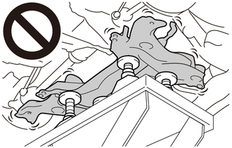
The front suspension crossmember sub-assembly is a very heavy component. Make sure that it is supported securely.
-
If the front suspension crossmember sub-assembly is not securely supported, it may drop, resulting in serious injury.
Note
Use attachments to keep the front suspension crossmember sub-assembly level.
-
-
Temporarily tighten the 2 bolts A while alternately inserting SST into the left and right side reference holes in the front suspension crossmember sub-assembly.
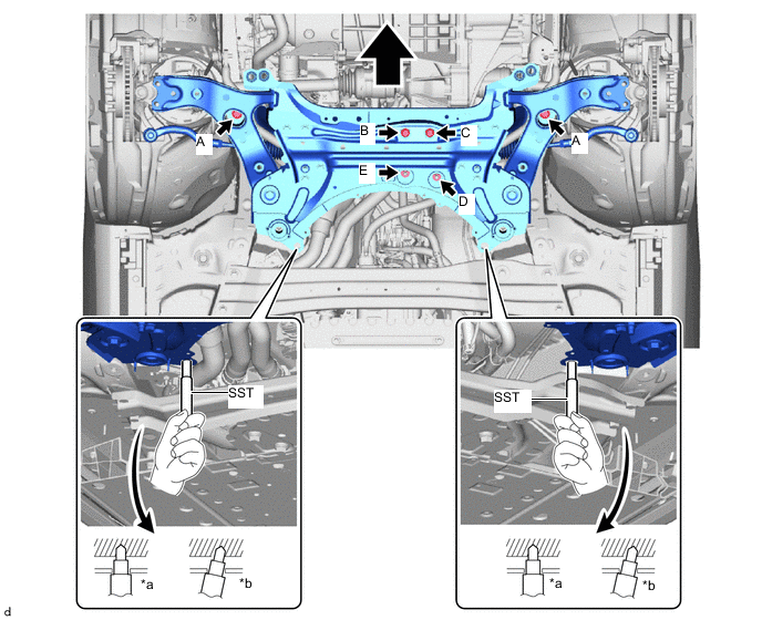
*a Correct *b Incorrect Front of the Vehicle - - - SST
- 09670-00020
- Torque:
- 137 N*m { 1397 kgf*cm, 101 ft.*lbf }
-
Lower the engine lifter.
-
Install the rear motor mounting insulator to the front suspension crossmember sub-assembly with the 2 bolts and 2 nuts.
- Torque:
- 72 N*m { 734 kgf*cm, 53 ft.*lbf }
Note
Temporarily tighten bolt B, and then fully tighten the 2 bolts and 2 nuts in the order of C, D, E, B.
-
-
INSTALL FRONT SUSPENSION MEMBER REAR BRACE LH
-
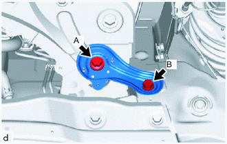
Install the front suspension member rear brace LH with the 2 bolts.
- Torque:
- Bolt A
- 137 N*m { 1397 kgf*cm, 101 ft.*lbf }
- Bolt B
- 93 N*m { 948 kgf*cm, 69 ft.*lbf }
Note
Temporarily tighten bolt A, and then fully tighten the 2 bolts in the order of B, A.
-
-
INSTALL FRONT SUSPENSION MEMBER REAR BRACE RH
Tech Tips
Use the same procedure for the RH side and LH side.
-
INSTALL FRONT CROSSMEMBER SUB-ASSEMBLY
-
Install the front cross member sub-assembly with the 4 bolts.
- Torque:
- 99 N*m { 1010 kgf*cm, 73 ft.*lbf }
-
Install the front cross member sub-assembly to the front motor mounting insulator with the 3 bolts.
- Torque:
- 72 N*m { 734 kgf*cm, 53 ft.*lbf }
-
-
INSTALL REAR SIDE RAIL REINFORCEMENT SUB-ASSEMBLY LH
-
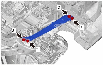
Install the rear side rail reinforcement sub-assembly LH with the 4 bolts.
- Torque:
- Bolt A, D
- 99 N*m { 1010 kgf*cm, 73 ft.*lbf }
- Bolt B, C
- 96 N*m { 979 kgf*cm, 71 ft.*lbf }
Note
Temporarily tighten bolt A and B, and then fully tighten the 4 bolts in the order of C, B, D, A.
-
-
INSTALL REAR SIDE RAIL REINFORCEMENT SUB-ASSEMBLY RH
-
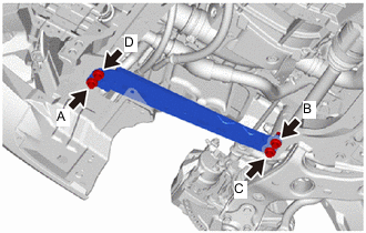
Install the rear side rail reinforcement sub-assembly RH with the 4 bolts.
- Torque:
- Bolt A, D
- 99 N*m { 1010 kgf*cm, 73 ft.*lbf }
- Bolt B, C
- 96 N*m { 979 kgf*cm, 71 ft.*lbf }
Note
Temporarily tighten bolt A and B, and then fully tighten the 4 bolts in the order of C, B, D, A.
-
Install the front fender splash shield sub-assembly RH with the clip.
-
-
CONNECT FRONT LOWER NO. 1 SUSPENSION ARM SUB-ASSEMBLY LH
-
CONNECT FRONT LOWER NO. 1 SUSPENSION ARM SUB-ASSEMBLY RH
Tech Tips
Use the same procedure for the RH side and LH side.
-
CONNECT TIE ROD END SUB-ASSEMBLY LH
-
CONNECT TIE ROD END SUB-ASSEMBLY RH
Tech Tips
Use the same procedure for the RH side and LH side.
-
CONNECT FRONT STABILIZER LINK ASSEMBLY LH
-
Install the front stabilizer link assembly LH with the nut.
- Torque:
- 74 N*m { 755 kgf*cm, 55 ft.*lbf }
Note
Do not damage the boot of the ball joint.
Tech Tips
If the ball joint turns together with the nut, use a 6 mm hexagon socket wrench to hold the stud bolt.
-
-
CONNECT FRONT STABILIZER LINK ASSEMBLY RH
Tech Tips
Use the same procedure for the RH side and LH side.
-
PLACE FRONT WHEELS FACING STRAIGHT AHEAD
-
INSTALL NO. 1 STEERING COLUMN HOLE COVER SUB-ASSEMBLY
-
CONNECT NO. 2 STEERING INTERMEDIATE SHAFT ASSEMBLY
-
INSTALL COLUMN HOLE COVER SILENCER SHEET
-
INSTALL FRONT WHEEL
-
STABILIZE SUSPENSION
-
FULLY TIGHTEN FRONT LOWER NO. 1 SUSPENSION ARM SUB-ASSEMBLY LH
-
FULLY TIGHTEN FRONT LOWER NO. 1 SUSPENSION ARM SUB-ASSEMBLY RH
Tech Tips
Use the same procedure for the RH side and LH side.
-
INSTALL FRONT FLOOR COVER RH
-
INSTALL FRONT FLOOR COVER LH
-
INSTALL REAR MOTOR UNDER COVER LH
-
Install the rear motor under cover LH to the vehicle with the 5 clips.
-
-
INSTALL REAR MOTOR UNDER COVER RH
-
Install the rear motor under cover RH to the vehicle with the 4 clips.
-
-
INSTALL NO. 2 MOTOR UNDER COVER
-
Install the No. 2 motor under cover to the vehicle with the 4 screws and 4 clips.
-
-
INSTALL NO. 1 MOTOR UNDER COVER
-
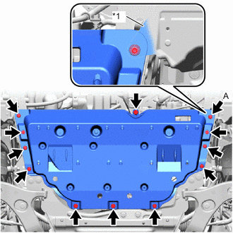
*1 Front Fender Splash Shield Sub-assembly LH Install the No. 1 motor under cover to the vehicle with the 3 bolts and 9 clips.
Tech Tips
Engage the clip A shown in the illustration to install the front fender splash shield sub-assembly over the No. 1 motor under cover.
-
-
INSTALL FRONT BUMPER LOWER ABSORBER
-
Install the front bumper lower absorber to the vehicle with the 8 bolts, 4 screws and 3 clips.
-
-
INSPECT AND ADJUST FRONT WHEEL ALIGNMENT
-
PERFORM YAW RATE AND ACCELERATION SENSOR CALIBRATION
-
ADJUST LANE RECOGNITION CAMERA SENSOR