FRONT SUSPENSION MEMBER REMOVAL

CAUTION / NOTICE / HINT
The necessary procedures (adjustment, calibration, initialization, or registration) that must be performed after parts are removed, installed, or replaced during the front suspension crossmember sub-assembly removal/installation are shown below.
| Replacement Part or Procedure | Necessary Procedure | Effects/Inoperative when not Performed | Link |
|---|---|---|---|
| Front wheel alignment adjustment |
|
VSC malfunctioning | |
| Adjust lane departure warning camera | Lane departure alert system does not operate correctly |
PROCEDURE
-
PLACE FRONT WHEELS FACING STRAIGHT AHEAD
-
SECURE STEERING WHEEL
-
REMOVE COLUMN HOLE COVER SILENCER SHEET
-
SEPARATE NO. 2 STEERING INTERMEDIATE SHAFT ASSEMBLY
-
SEPARATE NO. 1 STEERING COLUMN HOLE COVER SUB-ASSEMBLY
-
REMOVE FRONT WHEEL
-
REMOVE FRONT BUMPER LOWER ABSORBER
-
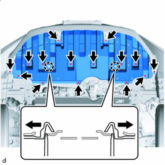

Push Remove the 8 bolts, 4 screws and 3 clips.
-
Using a screwdriver, disengage the 2 claws to remove the front bumper lower absorber as shown in the illustration.
-
-
REMOVE NO. 1 MOTOR UNDER COVER
-
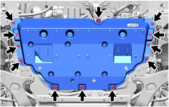
Remove the 3 bolts, 9 clips and No. 1 motor under cover from the vehicle.
-
-
REMOVE NO. 2 MOTOR UNDER COVER
-
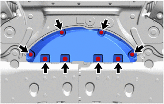
Remove the 4 screws, 4 clips and No. 2 motor under cover from the vehicle.
-
-
REMOVE REAR MOTOR UNDER COVER LH
-
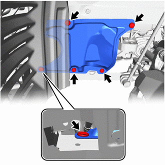
Remove the 5 clips and rear motor under cover LH from the vehicle.
-
-
REMOVE REAR MOTOR UNDER COVER RH
-
Remove the 4 clips and rear motor under cover RH from the vehicle.
-
-
REMOVE FRONT FLOOR COVER RH
-
REMOVE FRONT FLOOR COVER LH
-
SEPARATE FRONT STABILIZER LINK ASSEMBLY LH
-

Remove the nut and separate the front stabilizer link assembly LH from the front stabilizer bar.
Note
Do not damage the boot of the ball joint.
Tech Tips
If the ball joint turns together with the nut, use a 6 mm hexagon socket wrench to hold the stud bolt.
-
-
SEPARATE FRONT STABILIZER LINK ASSEMBLY RH
Tech Tips
Use the same procedure for the RH side and LH side.
-
SEPARATE TIE ROD END SUB-ASSEMBLY LH
-
SEPARATE TIE ROD END SUB-ASSEMBLY RH
Tech Tips
Use the same procedure for the RH side and LH side.
-
SEPARATE FRONT LOWER NO. 1 SUSPENSION ARM SUB-ASSEMBLY LH
-
SEPARATE FRONT LOWER NO. 1 SUSPENSION ARM SUB-ASSEMBLY RH
Tech Tips
Use the same procedure for the RH side and LH side.
-
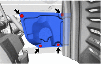
REMOVE REAR SIDE RAIL REINFORCEMENT SUB-ASSEMBLY LH
-
Remove the 4 bolts and rear side rail reinforcement sub-assembly LH.
-
-
REMOVE REAR SIDE RAIL REINFORCEMENT SUB-ASSEMBLY RH
-
Remove the clips and separate the front fender splash shield sub-assembly RH.
-
Remove the 4 bolts and rear side rail reinforcement sub-assembly RH.
-
-
SUPPORT FCV TRANSAXLE WITH MOTOR ASSEMBLY
-
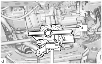
*a Wooden Block Using a transmission jack and wooden blocks, support the FCV transaxle with motor assembly.
CAUTION:
-
Do not remove the support before installing the front crossmember sub-assembly and front suspension crossmember sub-assembly.
-
If the support is removed, the FCV transaxle with motor assembly could fall.
-
-
-
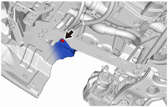
REMOVE FRONT CROSSMEMBER SUB-ASSEMBLY
-
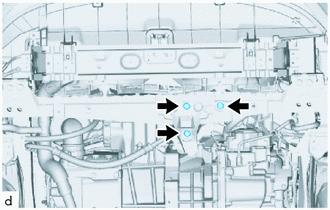
Remove the 3 bolts and separate the front motor mounting insulator from the front crossmember sub-assembly
-

Remove the 4 bolts and front crossmember sub-assembly from the vehicle.
-
-
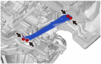
REMOVE FRONT SUSPENSION MEMBER REAR BRACE LH
-
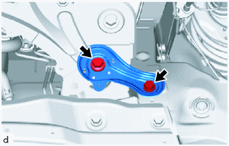
Remove the 2 bolts and front suspension member rear brace LH.
-
-
REMOVE FRONT SUSPENSION MEMBER REAR BRACE RH
Tech Tips
Use the same procedure for the RH side and LH side.
-
REMOVE FRONT SUSPENSION CROSSMEMBER SUB-ASSEMBLY
-
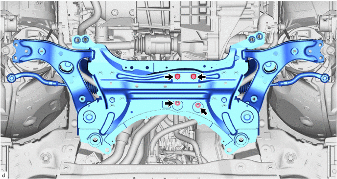
Remove the 2 bolts and 2 nuts and separate the rear motor mounting insulator from the front suspension crossmember sub-assembly.
-
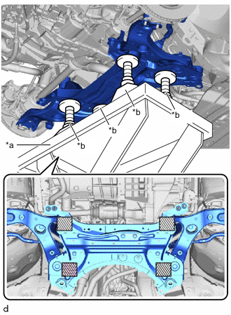
*a Engine Lifter *b Attachment 
Attachment placement location Support the front suspension crossmember sub-assembly with an engine lifter using 4 attachments or equivalent tools as shown in the illustration.
CAUTION:
-
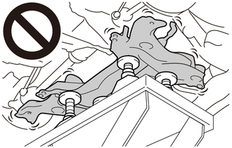
The front suspension crossmember sub-assembly is a very heavy component. Make sure that it is supported securely.
-
If the front suspension crossmember sub-assembly is not securely supported, it may drop, resulting in serious injury.
Note
Use attachments to keep the front suspension crossmember sub-assembly level.
-
-
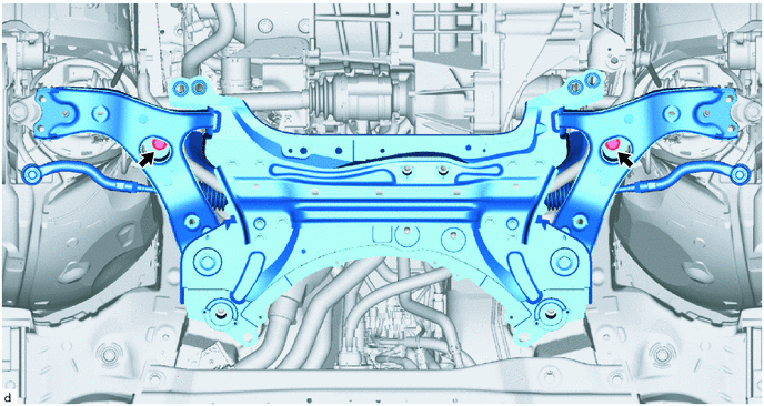
Remove the 2 bolts and front suspension crossmember sub-assembly with steering gear assembly.
-
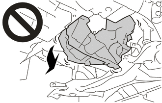
Slowly lower the front suspension crossmember sub-assembly.
Note
When lowering the front suspension crossmember sub-assembly, be careful not to damage the vehicle body or other components installed to the vehicle.
-
-
REMOVE FRONT LOWER NO. 1 SUSPENSION ARM SUB-ASSEMBLY LH
-
REMOVE FRONT LOWER NO. 1 SUSPENSION ARM SUB-ASSEMBLY RH
Tech Tips
Use the same procedure for the RH side and LH side.
-
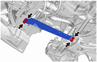
REMOVE FRONT SUSPENSION MEMBER BRACE
-
REMOVE FRONT STABILIZER BAR
-
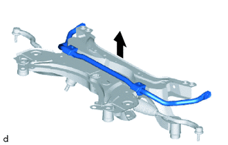
Remove the front stabilizer bar with front stabilizer bar bush LH and front stabilizer bar bush RH from the front suspension crossmember sub-assembly.
-
-
REMOVE STEERING LINK ASSEMBLY
-
REMOVE REAR CAB MOUNTING LOWER SPACER
-
Remove the 4 rear lower cab mounting spacers from the front suspension crossmember sub-assembly.
-
-
REMOVE REAR CAB MOUNTING CUSHION
-
Remove the 4 rear cab mounting cushions from the front suspension crossmember sub-assembly.
-
-
REMOVE FRONT SUSPENSION MEMBER BODY MOUNTING FRONT STOPPER
-
Remove the 2 front suspension member body mounting rear stoppers from the front suspension crossmember sub-assembly.
-
-
REMOVE FRONT SUSPENSION MEMBER BODY MOUNTING REAR STOPPER
-
Remove the 2 front suspension member body mounting rear stoppers from the front suspension member rear brace LH and front suspension member rear brace RH.
-
-
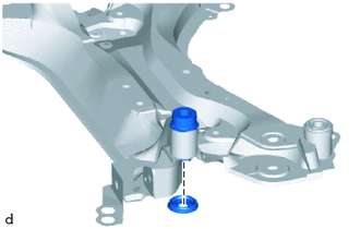
REMOVE FRONT UPPER BODY MOUNTING CUSHION
-
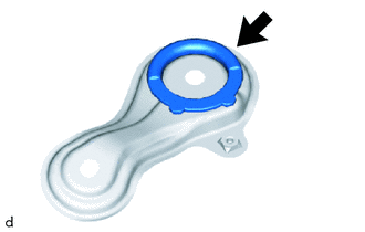
Using a chisel and hammer, kink the flange of the front upper body mounting cushion as shown in the illustration.
-
Apply lubricant to the contact surfaces of the front upper body mounting cushion.
-
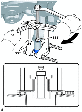
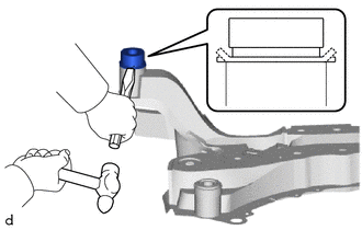
*a Hold *b Turn Position and firmly secure SST as shown in the illustration.
- SST
- 09950-00020
- 09950-00030
- 09950-40011 ( 09957-04010 )
- 09950-60010 ( 09951-00300 )
-
While applying lubricant to the contact surfaces between the front upper body mounting cushion and front suspension crossmember sub-assembly, gradually remove the front upper body mounting cushion.
Note
-
Be careful when removing the front upper body mounting cushion because it may unexpectedly pop out.
-
Do not reuse the front upper body mounting cushion.
-
-
-
REMOVE FRONT SUSPENSION MEMBER BODY MOUNTING REAR CUSHION
-
Apply lubricant to the contact surface of the front suspension member body mounting rear cushion.
-
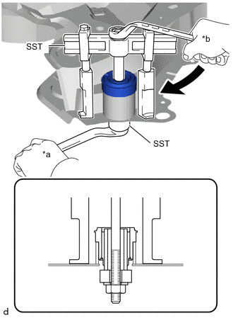
*a Hold *b Turn Position and firmly secure SST as shown in the illustration.
- SST
- 09710-28031 ( 09711-02030, 09711-02040, 94622-51200 )
- 09950-40011 ( 09951-04020, 09952-04010, 09954-04010, 09955-04031 )
- 09950-60010 ( 09951-00320 )
-
While applying lubricant to the contact surfaces between the front suspension member body mounting rear cushion and front suspension crossmember sub-assembly, gradually remove the front suspension member body mounting rear cushion.
Note
-
Be careful when removing the cushion because it may unexpectedly pop out.
-
Do not reuse the front suspension member body mounting rear cushion.
-
-