FRONT STABILIZER BAR INSTALLATION
PROCEDURE
-
INSTALL FRONT STABILIZER BAR BUSH LH
-
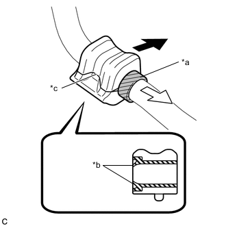
*a Stopper *b Dust Lip *c Cutout 
Front of the Vehicle 
Inside of the Vehicle Install the front stabilizer bar bush LH to the front stabilizer bar as shown in the illustration.
Note
-
Install the front stabilizer bar bush LH so that the cutout is facing the inside of the vehicle.
-
Install the front stabilizer bar bush LH so that the dust lip is facing the front of the vehicle.
-
-
-
INSTALL FRONT STABILIZER BAR BUSH RH
Tech Tips
Use the same procedure for the RH side and LH side.
-
INSTALL FRONT STABILIZER BAR
-
Install the front stabilizer bar to the front suspension crossmember sub-assembly.
Note
Make sure that the identification mark is positioned on the right side of the vehicle.
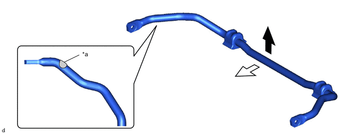
*a Identification Mark - - Top of the Vehicle Front of the Vehicle
-
-
INSTALL FRONT SUSPENSION MEMBER BRACE
-
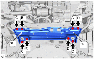
*a Protrusion Install the front suspension member brace with the 8 bolts.
- Torque:
- 92 N*m { 938 kgf*cm, 68 ft.*lbf }
Note
-
Temporarily tighten bolt A, and then fully tighten the 4 bolts in the order of B, C, D, A.
-
When installing the front suspension member brace, make sure the protrusion of the front stabilizer bar bush LH and front stabilizer bar bush RH is protruding.
-
-
TEMPORARILY TIGHTEN FRONT LOWER NO. 1 SUSPENSION ARM SUB-ASSEMBLY LH
-
INSTALL FRONT LOWER NO. 1 SUSPENSION ARM SUB-ASSEMBLY LH
-
INSTALL FRONT STABILIZER LINK ASSEMBLY LH
-
Install the front stabilizer link assembly LH with the 2 nuts.
- Torque:
- 74 N*m { 755 kgf*cm, 55 ft.*lbf }
Note
Do not damage the boot of the ball joint.
Tech Tips
If the ball joint turns together with the nut, use a 6 mm hexagon socket wrench to hold the stud bolt.
-
-
INSTALL FRONT STABILIZER LINK ASSEMBLY RH
Tech Tips
Use the same procedure for the RH side and LH side.
-
INSTALL FRONT WHEEL
-
STABILIZE SUSPENSION
-
FULLY TIGHTEN FRONT LOWER NO. 1 SUSPENSION ARM SUB-ASSEMBLY LH
-
INSTALL NO. 1 MOTOR UNDER COVER
-
INSPECT AND ADJUST FRONT WHEEL ALIGNMENT
-
PERFORM YAW RATE AND ACCELERATION SENSOR CALIBRATION
-
ADJUST LANE RECOGNITION CAMERA SENSOR