FRONT STABILIZER BAR REMOVAL
CAUTION / NOTICE / HINT
The necessary procedures (adjustment, calibration, initialization, or registration) that must be performed after parts are removed, installed, or replaced during the front stabilizer link assembly removal/installation are shown below.
| Replacement Part or Procedure | Necessary Procedure | Effects/Inoperative when not Performed | Link |
|---|---|---|---|
| Front wheel alignment adjustment |
|
VSC malfunctioning | |
| Adjust lane departure warning camera | Lane departure alert system does not operate correctly |
PROCEDURE
-
REMOVE FRONT WHEEL
-
REMOVE NO. 1 MOTOR UNDER COVER
-
REMOVE FRONT STABILIZER LINK ASSEMBLY LH
-
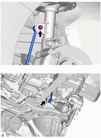
Remove the 2 nuts and front stabilizer link assembly LH.
Note
Do not damage the boot of the ball joint.
Tech Tips
If the ball joint turns together with the nut, use a 6 mm hexagon socket wrench to hold the stud bolt.
-
-
REMOVE FRONT STABILIZER LINK ASSEMBLY RH
Tech Tips
Use the same procedure for the RH side and LH side.
-
SEPARATE FRONT LOWER NO. 1 SUSPENSION ARM SUB-ASSEMBLY LH
-
REMOVE FRONT LOWER NO. 1 SUSPENSION ARM SUB-ASSEMBLY LH
-
REMOVE FRONT SUSPENSION MEMBER BRACE
-
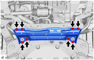
Remove the 8 bolts and front suspension member brace.
-
-
REMOVE FRONT STABILIZER BAR
-
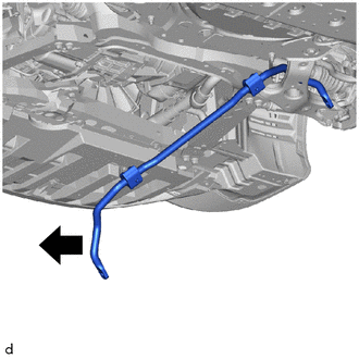
Remove the front stabilizer bar from the front suspension crossmember sub-assembly.
-
-
REMOVE FRONT STABILIZER BAR BUSH LH
-
Remove the front stabilizer bar bush LH from the front stabilizer bar.
-
-
REMOVE FRONT STABILIZER BAR BUSH RH
Tech Tips
Use the same procedure for the RH side and LH side.