FRONT LOWER BALL JOINT REMOVAL

CAUTION / NOTICE / HINT
The necessary procedures (adjustment, calibration, initialization, or registration) that must be performed after parts are removed, installed, or replaced during the front lower ball joint assembly removal/installation are shown below.
| Replacement Part or Procedure | Necessary Procedure | Effects/Inoperative when not Performed | Link |
|---|---|---|---|
| Front wheel alignment adjustment |
|
VSC malfunctioning | |
| Adjust lane departure warning camera | Lane departure alert system does not operate correctly |
Note
-
When removing or installing the front disc brake caliper assembly, if the piston of the brake caliper is pushed in, the clearance between the brake pad and front disc will become large. In this condition, depressing the brake pedal may cause DTC C1214 (Hydraulic Control System Malfunction) to be stored, so check and clear DTCs after the procedure is complete.
-
With the auxiliary battery connected, even if the power switch is off, turning a door courtesy switch ON or operating the brake pedal will activate the brake control system, so disconnect the negative auxiliary battery terminal so that brake control is prohibited.
Tech Tips
-
Use the same procedure for the RH side and LH side.
-
The following procedure is for the LH side.
PROCEDURE
-
REMOVE FRONT AXLE ASSEMBLY
-
REMOVE FRONT LOWER BALL JOINT ASSEMBLY
-
Secure the front axle assembly in a vise between aluminum plates.
Note
Do not overtighten the vise.
-
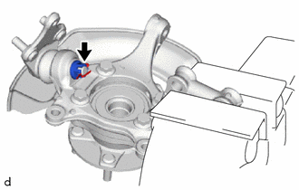
Remove the cotter pin and nut.
-
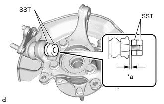
*a 1 mm (0.0394 in.) Install SST to the front lower ball joint assembly as shown in the illustration.
- SST
- 09960-20010 ( 09961-02050 )
Note
Check that the clearance measurement between SST and the front axle assembly is 1 mm (0.0394 in.).
-
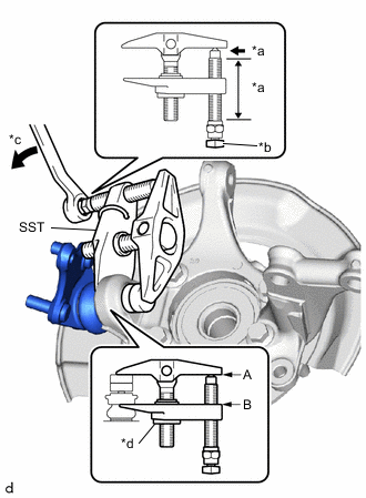
*a Molybdenum Grease Application Area *b Place wrench here *c Turn *d Center Nut Using SST, remove the front lower ball joint assembly from the front axle assembly as shown in the illustration.
- SST
- 09960-20010 ( 09961-02010, 09961-02050 )
CAUTION:
Apply molybdenum grease to the threads and end of the SST bolt.
Note
-
Install SST with the center nut so that (A) and (B) shown in the illustration are parallel. Otherwise, the front lower ball joint dust cover may be damaged.
-
Be sure to place a wrench on the part shown in the illustration.
-
Do not damage the front lower ball joint dust cover.
-
Do not damage the steering knuckle.
-
Do not damage the front disc brake dust cover.
-