FRONT AXLE HUB INSTALLATION
CAUTION / NOTICE / HINT
Note
When removing or installing the front disc brake caliper assembly, pushing back the disc brake piston may cause a large clearance between the brake pads and brake disc. When the brake pedal is depressed with a large clearance between the brake pads and the brake disc, DTCs C1214 related to abnormal brake fluid pressure may be stored. Make sure to clear DTCs after performing this step.
Tech Tips
-
Use the same procedure for the RH side and LH side.
-
The following procedure is for the LH side.
PROCEDURE
-
INSTALL FRONT AXLE HUB SUB-ASSEMBLY
-
Secure the steering knuckle between aluminum plates in a vise.
Note
Do not overtighten the vise.
-
Install the front axle hub sub-assembly and front disc brake dust cover to the steering knuckle with the 4 bolts.
- Torque:
- 96 N*m { 979 kgf*cm, 71 ft.*lbf }
-
-
INSTALL FRONT AXLE ASSEMBLY
-
Install the front axle assembly to the front shock absorber assembly with the 2 bolts and 2 nuts.
- Torque:
- 240 N*m { 2447 kgf*cm, 177 ft.*lbf }
Note
-
Do not apply lubricants to the steering knuckle and shock absorber contact surfaces.
-
While fixing the bolts in place, tighten and install the nuts.
Tech Tips
The bolts can be installed in either direction, however, make sure that they are both installed in the same direction.
-
-
INSTALL FRONT DRIVE SHAFT ASSEMBLY
-
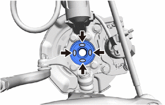
Apply TOYOTA body grease W to the entire contact surface between the front drive shaft assembly and front axle hub sub-assembly surface or only apply 0.1 to 0.3 g (0.00353 to 0.0105 oz.) of TOYOTA body grease W to the 4 areas on the axle hub bearing shown in the illustration.
-
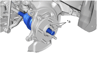
*a Matchmark Align the matchmarks on the front drive shaft assembly and front axle hub sub-assembly, and connect the front drive shaft assembly to the front axle assembly.
Note
-
Do not apply excessive force to the lower ball joint or front lower No. 1 suspension arm sub-assembly.
-
Do not push the front axle assembly towards the outside of the vehicle any further than necessary.
-
Do not damage the front disc brake dust cover.
-
Do not damage the front axle outboard joint boot.
-
Do not damage the front speed sensor rotor.
-
Check that there is no foreign matter on the front speed sensor rotor or contact surfaces.
-
-
-
INSTALL FRONT LOWER NO. 1 SUSPENSION ARM SUB-ASSEMBLY
-
CONNECT TIE ROD END SUB-ASSEMBLY
-
INSTALL FRONT DISC
-
INSTALL FRONT DISC BRAKE CALIPER ASSEMBLY
-
TEMPORARILY TIGHTEN FRONT AXLE SHAFT NUT
-
Clean the threaded parts on the front drive shaft assembly and a new front axle shaft nut using non-residue solvent.
Note
-
Be sure to perform this work even when using a new front drive shaft assembly.
-
Keep the threaded parts free of oil and foreign matter.
-
-
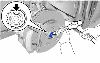
Using a 30 mm deep socket wrench, while applying the brakes, temporarily install the front axle shaft nut.
- Torque:
- 292 N*m { 2978 kgf*cm, 215 ft.*lbf }
Note
Stake the front axle shaft nut after inspecting for looseness and runout in the following steps.
Tech Tips
Keep depressing the brake pedal to prevent the front drive shaft assembly from rotating.
-
-
SEPARATE FRONT DISC BRAKE CALIPER ASSEMBLY
-
REMOVE FRONT DISC
-
INSPECT FRONT AXLE HUB BEARING LOOSENESS
-
INSPECT FRONT AXLE HUB RUNOUT
-
INSTALL FRONT DISC
-
INSTALL FRONT DISC BRAKE CALIPER ASSEMBLY
-
CONNECT FRONT FLEXIBLE HOSE
-
INSTALL FRONT SPEED SENSOR
-
INSTALL FRONT AXLE SHAFT NUT
-
Using a chisel and hammer, stake the front axle shaft nut.
-
-
INSTALL FRONT WHEEL
-
CONNECT CABLE TO NEGATIVE AUXILIARY BATTERY TERMINAL
-
INSTALL LUGGAGE TRIM SERVICE HOLE COVER
-
INSPECT AND ADJUST FRONT WHEEL ALIGNMENT
-
CHECK FOR SPEED SENSOR SIGNAL