FRONT DRIVE SHAFT ASSEMBLY INSTALLATION

CAUTION / NOTICE / HINT
Tech Tips
-
Use the same procedure for the RH side and LH side.
-
The following procedure is for the LH side.
PROCEDURE
-
INSTALL FRONT DRIVE INBOARD JOINT HOLE SNAP RING
-
Install a new front drive inboard joint hole snap ring to the front drive shaft assembly.
Note
Front drive inboard joint hole snap ring should be installed completely.
-
-
INSTALL FRONT DRIVE SHAFT ASSEMBLY
Tech Tips
Install so that the gap between the front drive inboard joint assembly and the FCV transaxle with motor assembly is the same as the gap measured at the time of removal.
-
Coat the splines of the front drive inboard joint assembly with ATF WS.
-
Coat the front drive inboard joint hole snap ring of the front drive inboard joint assembly with MP grease.
-
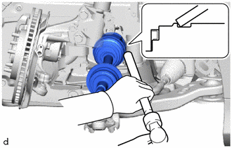
Align the front drive shaft assembly splines and FCV transaxle with motor assembly splines and tap in the front drive shaft assembly with a brass bar and hammer.
Note
-
Face the end gap of the front drive inboard joint hole snap ring downward.
-
Do not damage the front drive shaft oil seal.
-
Do not damage the front axle inboard joint boot.
-
Make sure to center the front drive shaft assembly during installation to prevent damage to the front drive inboard joint hole snap ring.
-
-
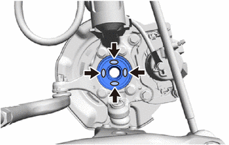
Apply TOYOTA body grease W to the entire contact surface between the front drive shaft assembly and front axle hub sub-assembly surface or only apply 0.1 to 0.3 g (0.00353 to 0.0105 oz.) of TOYOTA body grease W to the 4 areas on the axle hub bearing shown in the illustration.
-
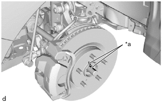
*a Matchmark Push the front axle assembly toward the outside of the vehicle, align the matchmarks of the front drive shaft assembly and the front axle assembly, and insert the front drive shaft assembly into the front axle assembly.
Note
-
Do not push the front axle assembly further out of the vehicle than is necessary.
-
Be careful not to damage the front axle outboard joint boot.
-
Be careful not to damage the front speed sensor rotor.
-
Check that there is no foreign matter on the contact surfaces.
-
-
-
CONNECT FRONT STABILIZER LINK ASSEMBLY
-
CONNECT FRONT LOWER NO. 1 SUSPENSION ARM SUB-ASSEMBLY
-
CONNECT TIE ROD END SUB-ASSEMBLY
-
INSTALL FRONT FLEXIBLE HOSE
-
CONNECT FRONT SPEED SENSOR
-
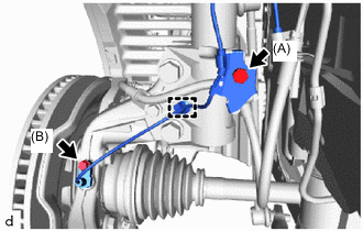
Connect the front flexible hose and front speed sensor to the steering knuckle with the bolt (A).
- Torque:
- 18.8 N*m { 192 kgf*cm, 14 ft.*lbf }
Note
-
Connect the front flexible hose first.
-
Do not twist the front flexible hose and front speed sensor.
-
Engage the clamp to connect the front speed sensor to the front shock absorber assembly.
-
Install the front speed sensor to the steering knuckle with the bolt (B).
- Torque:
- 8.5 N*m { 87 kgf*cm, 75 in.*lbf }
Note
-
Be careful not to damage the front speed sensor rotor.
-
Prevent foreign matter from attaching to the front speed sensor tip.
-
Do not twist the front speed sensor wire harness.
-
-
INSTALL FRONT AXLE SHAFT NUT
-
Clean the threaded parts on the front drive shaft assembly and a new front axle shaft nut using non-residue solvent.
Note
-
Make sure to perform this work even when using a new front drive shaft assembly.
-
Keep the threaded parts free of oil and foreign matter.
-
-
Using a 30 mm deep socket wrench, install the front axle shaft nut.
- Torque:
- 292 N*m { 2978 kgf*cm, 215 ft.*lbf }
-
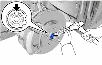
Using a chisel and hammer, stake the front axle shaft nut.
-
-
ADD HYBRID TRANSAXLE FLUID
-
INSPECT AND ADJUST HYBRID TRANSAXLE FLUID
-
INSTALL NO. 1 MOTOR UNDER COVER
-
INSTALL FRONT WHEEL
-
INSPECT AND ADJUST FRONT WHEEL ALIGNMENT
-
CHECK FOR SPEED SENSOR SIGNAL