FRONT DRIVE SHAFT ASSEMBLY REASSEMBLY

CAUTION / NOTICE / HINT
Note
-
When using a vise, place aluminum plates between the part and vise.
-
When using a vise, do not overtighten it.
PROCEDURE
-
INSTALL FRONT DRIVE SHAFT DUST COVER LH
-
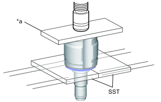
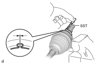
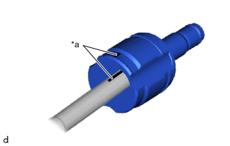
*a Steel Plate Using SST, a press and a steel plate, install a new front drive shaft dust cover LH to the front drive inboard joint assembly LH.
- SST
- 09527-10011
Note
-
Install the front drive shaft dust cover in the correct orientation.
-
Make sure to fully install the front drive shaft dust cover LH.
-
Be careful not to damage the front drive shaft dust cover LH.
-
-
INSTALL FRONT DRIVE SHAFT DUST COVER RH
Tech Tips
Use the same procedure described for the LH side.
-
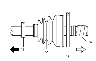
INSTALL FRONT AXLE OUTBOARD JOINT BOOT (for LH Side)
-
*a Protective Tape Wrap the splines of the front drive outboard joint shaft assembly LH with protective tape to prevent the front axle outboard joint boot from being damaged.
-
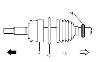
*1 Front Drive Outboard Joint Shaft Assembly LH *2 Front No. 2 Axle Outboard Joint Boot LH Clamp *3 Front Axle Outboard Joint Boot *4 Front Axle Outboard Joint Boot LH Clamp 
Outboard joint side 
Inboard joint side Install new parts to the front drive outboard joint shaft assembly LH in the following order as shown in the illustration.
-
Front No. 2 axle outboard joint boot LH clamp
-
Front axle outboard joint boot
-
Front axle outboard joint boot LH clamp
-
-
Pack the joint portion of the front drive outboard joint shaft assembly LH and front axle outboard joint boot with grease.
Standard Grease Capacity 115 to 135 g (4.06 to 4.76 oz.) -
Install the front axle outboard joint boot to the front drive outboard joint shaft assembly LH groove.
Note
-
Do not apply grease to the part of the front axle outboard joint boot that contacts the groove.
-
Do not allow foreign matter to enter the front axle outboard joint boot.
-
-
-
INSTALL FRONT NO. 2 AXLE OUTBOARD JOINT BOOT LH CLAMP
-
Install SST to the front No. 2 axle outboard joint boot LH clamp, and then while pressing the front axle outboard joint boot, slightly tighten the SST bolt.
- SST
- 09521-24010
Note
-
Correctly set the front No. 2 axle outboard joint boot LH clamp to the guide groove.
-
Do not damage the front axle outboard joint boot.
-
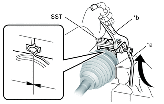
*a Turn *b Hold Tighten SST so that the front No. 2 axle outboard joint boot LH clamp is pinched.
Standard Clearance 1.2 to 4.0 mm (0.0473 to 0.157 in.) Note
-
When tightening SST, make sure the clearance of the front No. 2 axle outboard joint boot LH clamp is within the standard clearance.
-
Do not damage the front axle outboard joint boot.
-
-
Remove SST from the front No. 2 axle outboard joint boot LH clamp.
-
Using SST, measure the clearance of the front No. 2 axle outboard joint boot LH clamp.
- SST
- 09240-00020
Standard Clearance 1.2 to 4.0 mm (0.0473 to 0.157 in.) Note
-
If the measured value exceeds the specified value, retighten the front No. 2 axle outboard joint boot LH clamp.
-
If the result is lower than the specified range, install a new front No. 2 axle outboard joint boot LH clamp.
-
-
INSTALL FRONT AXLE OUTBOARD JOINT BOOT LH CLAMP
Tech Tips
Use the same procedure described for the front No. 2 axle outboard joint boot LH clamp.
-
INSTALL FRONT DRIVE INBOARD JOINT ASSEMBLY LH
-
*1 Front Axle Inboard Joint Boot LH Clamp *2 Front Axle Inboard Joint Boot *3 Front No. 2 Axle Inboard Joint Boot LH Clamp *a Protective Tape Outboard joint side Inboard joint side Install new parts to the front drive outboard joint shaft assembly LH in the following order as shown in the illustration.
-
Front axle inboard joint boot LH clamp
-
Front axle inboard joint boot
-
Front No. 2 axle inboard joint boot LH clamp
-
-
Secure the front drive outboard joint shaft assembly LH in a vise between aluminum plates.
Note
Do not overtighten the vise.
-
Remove the protective tape.
-
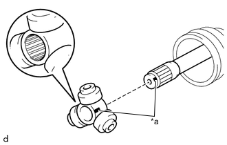
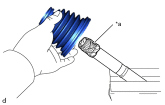
*a Matchmark Align the matchmarks and install the tripod joint to the front drive outboard joint shaft assembly LH.
Note
Face the serrated side of the tripod joint outward and install it to the outboard joint end.
-
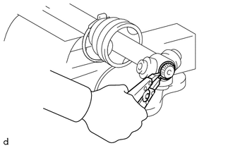
Using a brass bar and a hammer, install the tripod joint to the front drive outboard joint shaft assembly LH.
Note
-
Do not tap the rollers.
-
Keep the tripod joint free of foreign matter.
-
Make sure to install the tripod joint the correct direction.
-
-
Using a snap ring expander, install a new front drive inner shaft inner LH shaft snap ring to the front drive outboard joint shaft assembly LH.
Note
The front drive inner shaft inner LH shaft snap ring should be installed completely.
-
Pack the front drive inboard joint assembly LH and front axle inboard joint boot with grease.
Standard Grease Capacity 190 to 210 g (6.70 to 7.40 oz) -
*a Matchmark Align the matchmarks and install the front drive inboard joint assembly LH to the front drive outboard joint shaft assembly LH.
-
-
INSTALL FRONT DRIVE INBOARD JOINT ASSEMBLY RH
Tech Tips
Use the same procedure described for the LH side.
-
INSTALL FRONT AXLE INBOARD JOINT BOOT
Tech Tips
Use the same procedure for the RH side and LH side.
-
Install the front axle inboard joint boot to the front drive inboard joint assembly.
Note
-
Keep the inside of the front axle inboard joint boot free of foreign matter.
-
Keep the grooves free of grease.
-
-
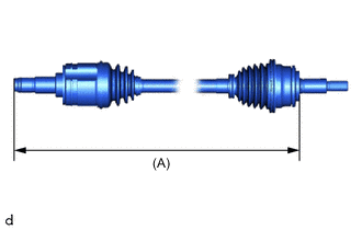
Check whether the dimension (A) of each front drive shaft assembly is within specification.
Dimension (A) Item Length for LH Side 584.6 mm (1.92 ft.) for RH Side 866.9 mm (2.84 ft.)
-
-
INSTALL FRONT NO. 2 AXLE INBOARD JOINT BOOT LH CLAMP
-
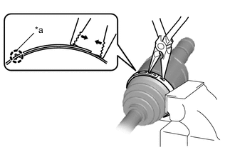
*a Claw Install the front No. 2 axle inboard joint boot LH clamp to the front axle inboard joint boot.
Note
Correctly set the front No. 2 axle inboard joint boot LH clamp to the guide groove.
-
Using needle-nose pliers, hold the front No. 2 axle inboard joint boot LH clamp at the claw engagement.
Note
-
Do not damage the front axle inboard joint boot.
-
Do not deform the claw engagement of the front No. 2 axle inboard joint boot LH clamp.
-
-
-
INSTALL FRONT NO. 2 AXLE INBOARD JOINT BOOT RH CLAMP
Tech Tips
Use the same procedure described for the LH side.
-
INSTALL FRONT AXLE INBOARD JOINT BOOT LH CLAMP
-
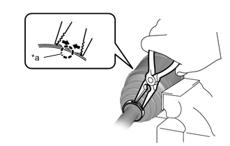
*a Claw Install the front axle inboard joint boot LH clamp to the front axle inboard joint boot.
Note
Correctly set the front axle inboard joint boot LH clamp to the guide groove.
-
Using needle-nose pliers, hold the front axle inboard joint boot LH clamp at the claw engagement.
Note
-
Do not damage the front axle inboard joint boot.
-
Do not deform the claw engagement of the front axle inboard joint boot LH clamp.
-
-
-
INSTALL FRONT AXLE INBOARD JOINT BOOT RH CLAMP
Tech Tips
Use the same procedure described for the LH side.
-
INSPECT FRONT DRIVE SHAFT ASSEMBLY