FRONT LOWER SUSPENSION ARM INSTALLATION
CAUTION / NOTICE / HINT
Tech Tips
-
Use the same procedure for the RH side and LH side.
-
The following procedure is for the LH side.
PROCEDURE
-
TEMPORARILY TIGHTEN FRONT LOWER NO. 1 SUSPENSION ARM SUB-ASSEMBLY
-
Temporarily install the front lower No. 1 suspension arm sub-assembly to the front suspension crossmember sub-assembly with the 2 bolts and nut.
Note
Because the nut has its own stopper, do not turn the nut. Tighten the bolt with the nut secured.
-
-
INSTALL FRONT LOWER NO. 1 SUSPENSION ARM SUB-ASSEMBLY
-
Install the front lower No. 1 suspension arm sub-assembly to the front lower ball joint assembly with the bolt and 2 nuts.
- Torque:
- 92 N*m { 938 kgf*cm, 68 ft.*lbf }
-
-
INSTALL FRONT WHEEL
-
STABILIZE SUSPENSION
-
FULLY TIGHTEN FRONT LOWER NO. 1 SUSPENSION ARM SUB-ASSEMBLY
-
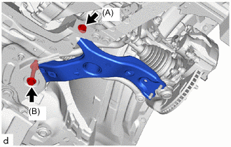
Fully tighten the bolt (A).
- Torque:
- 233 N*m { 2376 kgf*cm, 172 ft.*lbf }
-
Fully tighten the bolt (B).
- Torque:
- 214 N*m { 2182 kgf*cm, 158 ft.*lbf }
Note
Because the nut has its own stopper, do not turn the nut. Tighten the bolt with the nut secured.
-
-
INSTALL NO. 1 MOTOR UNDER COVER
-
INSPECT AND ADJUST FRONT WHEEL ALIGNMENT
-
PERFORM YAW RATE AND ACCELERATION SENSOR CALIBRATION
-
ADJUST LANE RECOGNITION CAMERA SENSOR