MILLIMETER WAVE RADAR SENSOR ADJUSTMENT

PROCEDURE
-
PREPARATION FOR MILLIMETER WAVE RADAR SENSOR ASSEMBLY ADJUSTMENT
-
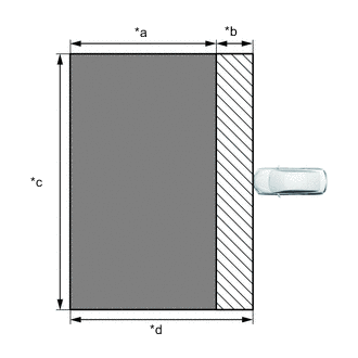
*a Approx. 8 m (26.2 ft.) *b Approx. 2 m (6.56 ft.) *c Approx. 14 m (45.9 ft.) *d Approx. 10 m (32.8 ft.) 
Floor where metal objects of 50 mm or smaller cannot be placed. 
Floor where metal objects of 50 mm or smaller can be placed. As shown in the illustration, perform the work in a location where the floor is flat and level, and with no metallic objects nearby or on the surface of the floor.
Tech Tips
Metal gutter covers, etc. within 2 m of the front of the vehicle will not affect the calibration.
-
Check the levelness of the floor.
-
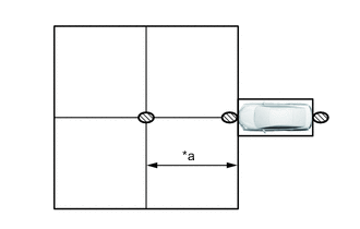
*a Approx. 5 m (16.4 ft.) Check Location As shown in the illustration, check the levelness of the floor in 3 places: at a point 5 m in front of the vehicle, at the front edge of the vehicle and at the rear edge of the vehicle.
-
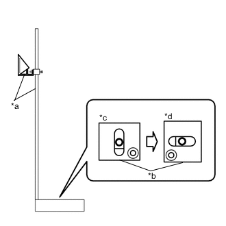
*a SST(Reflector) *b Level *c Side-to-side Direction *d Front-to-back Direction Place SST (reflector) at a position 5 meters in front of the vehicle, and as shown in the illustration, place a level on the base of SST (reflector) and check the levelness in 2 horizontal directions.
- SST
- 09870-60000 ( 09870-60010 )
- 09870-60040
-
Use the same procedure to check the levelness of the floor at the positions at the front edge and rear edge of the vehicle.
-
-
Make sure no extra loads are in the vehicle.
-
Adjust the tire pressures to the specified pressure.
-
Measure the vehicle height.
-
-
MILLIMETER WAVE RADAR SENSOR ASSEMBLY VERTICAL ADJUSTMENT
-
Remove the cool air intake duct seal.
-
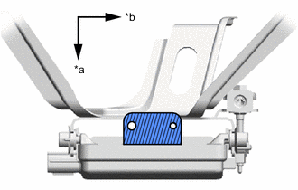
*a Vehicle Front *b Vehicle Left Level shelf Clean off any dust or oil adhering to the level shelf of the millimeter wave radar sensor assembly.
-
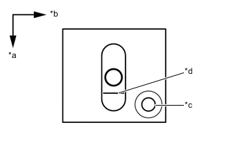
*a Vehicle Front *b Vehicle Left *c Hole *d Red Frame Place the level in the middle of the level shelf of the millimeter wave radar sensor assembly.
Tech Tips
As shown in the illustration, use the side of the level body with the hole for the vehicle front side, set the level to the millimeter wave radar sensor assembly, and perform calibration.
-
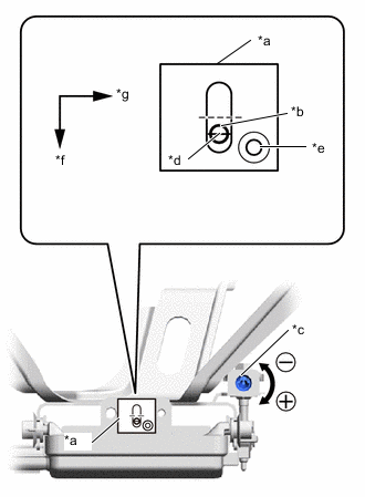
*a Level *b Air Bubble *c Bolt *d Red Frame *e Hole *f Vehicle Front *g Vehicle Left Using a screwdriver, rotate the vertical adjustment bolt of the millimeter wave radar sensor assembly to adjust the angle so that the air bubble is on the baseline (red line) of the level.
Standard 0.2° upward Tech Tips
By aligning the air bubble with the center of the reference line (red line), the angle becomes 0.2° upward.
Upward Turn screwdriver to positive (+) side When screwdriver is turned once, angle changes approx. 0.12° Downward Turn screwdriver to negative (-) side -
Install the cool air intake duct seal.
-
-
MILLIMETER WAVE RADAR SENSOR ASSEMBLY HORIZONTAL ADJUSTMENT
-
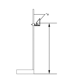
*a SST(Reflector) Adjust the SST (reflector) height.
-
Adjust the reflector so that the center of SST (reflector) is the same height as the millimeter wave radar sensor.
Reference Value 711 mm (2.33 ft.) - SST
- 09870-60000 ( 09870-60010 )
- 09870-60040
-
-
Place the SST (reflector).
-
From the center of the rear bumper (center of the emblem), hang a weight with a pointed tip, and mark point A on the ground.
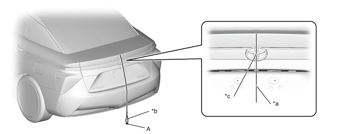
*a String *b Weight *c Center point - - Tech Tips
Lightly flick the string with your fingers several times to confirm that it is perpendicular with the ground.
-
From the center of the front bumper (center of the emblem), hang a weight with a pointed tip, and mark point B on the ground.
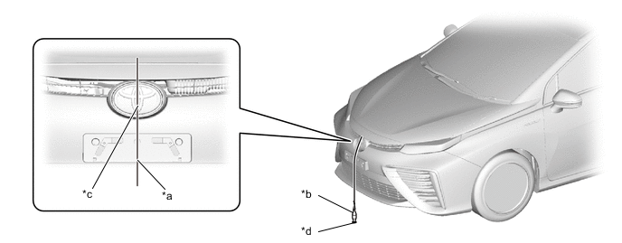
*a String *b Weight *c Center point - - Tech Tips
Lightly flick the string with your fingers several times to confirm that it is perpendicular with the ground.
-
Using point A as the starting point, make a straight line of string that passes through point B and ends at a position at least 5000 mm (16.4 ft.) past the B point in front of the vehicle, and secure the string to the floor.
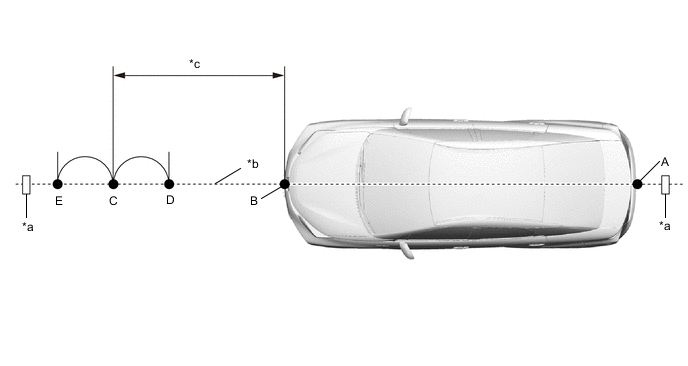
*a Tape *b String *c 5000 mm (16.4 ft.) - - Tech Tips
-
Pull the string taut, and secure it using tape, etc.
-
Lightly flick the string with your fingers several times to confirm that the string is aligned with point B.
-
-
As shown in the illustration, mark point C, which is the standard position for setting SST (reflector), at a point 5000 mm (16.4 ft.) in front of point B.
-
As shown in the illustration, using point C as the center, mark point D and point E at equal distances to the front and rear.
-
To mark a straight line perpendicular to the vehicle's axis, use a string as shown in the illustration, and using point D as the center, mark line G.
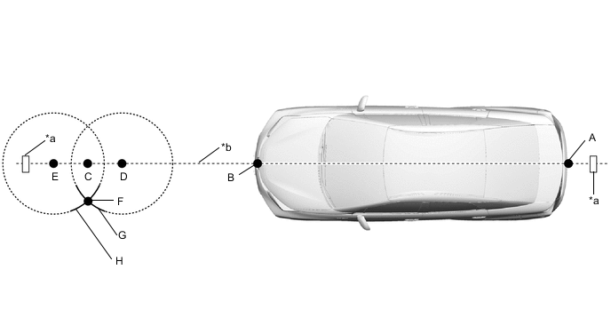
*a Tape *b String -
As shown in the illustration, using a piece of string the same length as the one used to mark line G, mark line H using point E as the center.
-
Mark point F at the point where line G and line H intersect.
-
Using a piece of string, make a straight line perpendicular to the vehicle axis and passing through point C and point F, and secure the string to the floor.
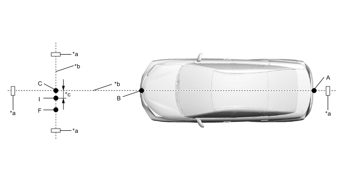
*a Tape *b String *c 11 mm (0.433 in.) - - Tech Tips
Pull the string taut, and secure it using tape, etc.
-
As shown in the illustration, mark point I at a position 11 mm (0.433 in.) from point C.
Tech Tips
Because the millimeter wave radar sensor assembly is offset from the vehicle centerline, place the mark at a position offset from point C by 11 mm (0.433 in.) toward the passenger side.
-
Place the SST (reflector) at point I.
-
-
Check the radar beam axis.
-
Connect the GTS to the DLC3.
-
Turn the power switch on (IG).
-
Turn the GTS on and turn the cruise control main switch on.
-
Select "Connect to Vehicle".
-
Select each item on the display screen and proceed to the next screen.
-
Under "System Selection Menu", select "Radar Cruise".
-
Select "Utility" from the display screen.
-
Select "Beam Axis Adjustment" and proceed to the next screen.
-
Follow the instructions on the screen and continue with the procedure.
Tech Tips
Automatically performed by the driving support ECU according to GTS instructions.
Powertrain > Radar Cruise > UtilityTester Display Beam Axis Adjustment -
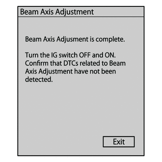
When the screen shown in the illustration is displayed, press the button to complete the camera axis adjustment.
-
-
Check the beam radar axis misalignment.
-
For the items that were removed from the vehicle, return them to the vehicle now.
-
Select "Connect to Vehicle".
-
Select each item on the display screen and proceed to the next screen.
-
Under "System Selection Menu", select "Radar Cruise".
-
Select "Utility" from the display screen.
-
Select "Beam Axis Misalignment Reading" and proceed to the next screen.
-
Follow the instructions on the screen and continue with the procedure.
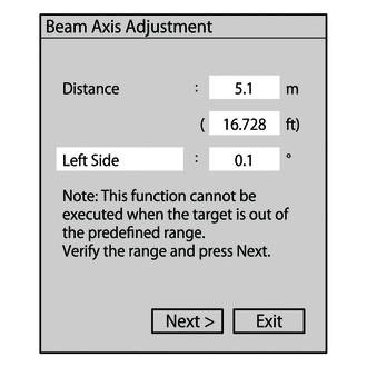
Powertrain > Radar Cruise > UtilityTester Display Beam Axis Misalignment Reading Reference value for camera axis deviation amount Left/Right: 0.1° Tech Tips
-
If the target distance or left-right camera axis deviation amount are not within allowable limits, the system may be selecting a target other than the SST (reflector), so check again that there are no reflective objects nearby.
-
Due to limitations of the GTS display, even if the left/right amount is less than 0.1°, Left/Right: 0.1° will be displayed.
-
-
Turn the power switch off (IG).
-
Disconnect the GTS from the DLC3.
-
-