DYNAMIC RADAR CRUISE CONTROL SYSTEM Cruise Control Switch Circuit
DESCRIPTION
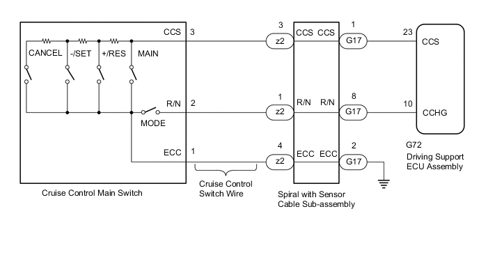
The cruise control main switch is used to turn the dynamic radar cruise control system on and off, as well as operate 8 functions: SET, -(COAST), TAP-DOWN, RES (RESUME), + (ACCEL), TAP-UP, CANCEL and MODE. The SET, TAP-DOWN and - (COAST) functions, and the RES (RESUME), TAP-UP and + (ACCEL) functions are operated with the same switch. The cruise control main switch is an automatic return type switch which turns on only while it is being operated and turns off when it is released. The driving support ECU assembly then reads the voltage value that has been changed by the switch operation to control MODE, SET, -, RES, +, or CANCEL function. The dynamic radar cruise control system has 2 cruise control modes: constant speed control mode and vehicle-to-vehicle distance control mode.
-
Vehicle-to-vehicle distance control mode is selected by default when the dynamic radar cruise control system is turned on using the cruise control main switch.
-
The operation of constant speed control mode is the same as that for a conventional cruise control system.
WIRING DIAGRAM
CAUTION / NOTICE / HINT
Note
-
The vehicle is equipped with a Supplemental Restraint System (SRS) which includes components such as airbags. Before servicing (including removal or installation of parts), be sure to read the precaution for Supplemental Restraint System.
-
When replacing the driving support ECU assembly, always replace it with a new one. If a driving support ECU assembly which was installed to another vehicle is used, the information stored in the driving support ECU assembly will not match the information from the vehicle. As a result, a DTC may be stored.
PROCEDURE
-
READ VALUE USING GTS
-
Connect the GTS to the DLC3.
-
Turn the power switch on (IG).
-
Turn the GTS on.
-
Enter the following menus: Powertrain / Radar Cruise / Data List.
-
Read the Data List according to the display on the Techstream.
Powertrain > Radar Cruise > Data ListTester Display Measurement Item Range Normal Condition Diagnostic Note Cruise Control Main Switch Cruise control switch signal ON or OFF ON: Cruise control main switch pushed
OFF: Cruise control main switch released
- RES/ACC Switch +RES switch signal ON or OFF ON: +RES switch on
OFF: +RES switch off
- SET/COAST Switch -SET switch signal ON or OFF ON: -SET switch on
OFF: -SET switch off
-
Powertrain > Radar Cruise > Data ListTester Display Cruise Control Main Switch RES/ACC Switch SET/COAST Switch OK When the cruise control main switch is operated, the display changes as shown above. Result Proceed to OK NG
OK 
PROCEED TO NEXT SUSPECTED AREA SHOWN IN PROBLEM SYMPTOMS TABLE Click here
NG 
-
-
INSPECT CRUISE CONTROL MAIN SWITCH
-
Remove the cruise control main switch.
-
Inspect the cruise control main switch.
Result Proceed to OK NG
NG
REPLACE CRUISE CONTROL MAIN SWITCH Click here
OK
-
-
INSPECT CRUISE CONTROL SWITCH WIRE
-
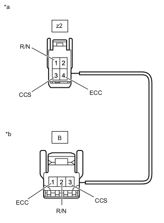
*a Front view of wire harness connector
(to Spiral Cable with Sensor Sub-assembly)
*b Front view of wire harness connector
(to Cruise Control Main Switch)
Remove the cruise control switch wire.
-
Measure the resistance according to the value(s) in the table below.
Standard Resistance Tester Connection Condition Specified Condition z2-1 (R/N) - B-2 (R/N) Always Below 1 Ω z2-3 (CCS) - B-3 (CCS) Always Below 1 Ω z2-4 (ECC) - B-1 (ECC) Always Below 1 Ω z2-1 (R/N) or B-2 (R/N) - Body ground Always 10 kΩ or higher z2-3 (CCS) or B-3 (CCS) - Body ground Always 10 kΩ or higher z2-4 (ECC) or B-1 (ECC) - Body ground Always 10 kΩ or higher Result Proceed to OK NG
NG
REPLACE CRUISE CONTROL SWITCH WIRE Click here
OK
-
-
INSPECT SPIRAL CABLE WITH SENSOR SUB-ASSEMBLY
-
Remove the spiral cable with sensor sub-assembly.
-
Inspect the spiral cable with sensor sub-assembly.
Click here
Result Proceed to OK NG
NG
REPLACE SPIRAL CABLE WITH SENSOR SUB-ASSEMBLY Click here
OK
-
-
CHECK HARNESS AND CONNECTOR (SPIRAL CABLE WITH SENSOR SUB-ASSEMBLY - DRIVING SUPPORT ECU ASSEMBLY AND BODY GROUND)
-
Disconnect the G17 spiral cable with sensor sub-assembly connector.
-
Disconnect the G72 driving support ECU assembly connector.
-
Measure the resistance according to the value(s) in the table below.
Standard Resistance Tester Connection Condition Specified Condition G17-1 (CCS) - G72-23 (CCS) Always Below 1 Ω G17-8 (R/N) - G72-10 (CCHG) Always Below 1 Ω G17-2 (ECC) - Body ground Always Below 1 Ω G17-1 (CCS) or G72-23 (CCS) - Body ground Always 10 kΩ or higher G17-8 (R/N) or G72-10 (CCHG) - Body ground Always 10 kΩ or higher Result Result Proceed to NG A OK (for LHD) B OK (for RHD) C
A
REPAIR OR REPLACE HARNESS OR CONNECTOR
B
REPLACE DRIVING SUPPORT ECU ASSEMBLY Click here
C
REPLACE DRIVING SUPPORT ECU ASSEMBLY Click here
-