RADIATOR INSTALLATION
PROCEDURE
-
INSTALL LOWER RADIATOR SUPPORT
-
Install the 2 lower radiator supports to the FC radiator assembly.
-
-
INSTALL RADIATOR SUPPORT CUSHION
-
Install the 2 radiator support cushions to the FC radiator assembly.
-
-
INSTALL FC RADIATOR ASSEMBLY
-
Engage the 3 guides to install the fan with motor to the FC radiator assembly.
-
Engage the clamp.
-
Install the 4 bolts.
- Torque:
- 7.0 N*m { 71 kgf*cm, 62 in.*lbf }
-
To prevent contamination by foreign matter or water droplets, remove the plastic bags from the connecting portions of the radiator reservoir tank hose and FC radiator assembly immediately before performing the procedure.
-
Connect the radiator reservoir tank hose to the FC radiator assembly.
Tech Tips
When connecting, if it is difficult to insert the radiator reservoir tank hose, coat it with new coolant (Toyota genuine FC stack coolant).
-
To prevent contamination by foreign matter or water droplets, remove the plastic bags from the connecting portions of the No. 1 FC radiator outlet hose and FC radiator assembly immediately before performing the procedure.
-
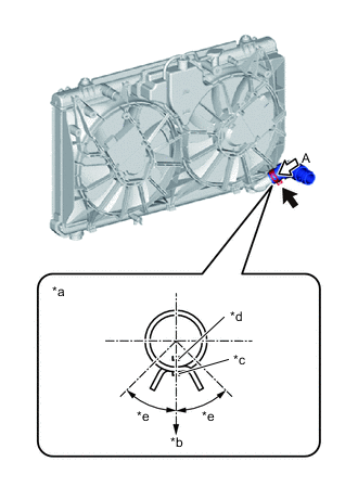
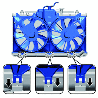
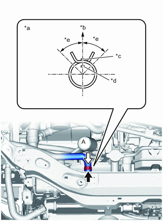
*a View A *b Bottom of Vehicle *c FC Radiator Assembly Rib *d Hose Paint Mark (White) *e Claw should be within this range (45°) Install the No. 1 FC radiator outlet hose to the FC radiator assembly and slide the hose clip to secure it.
Note
Align the hose and the hose clip at the locations shown in the illustration and install them.
Tech Tips
When connecting, if it is difficult to insert the No. 1 FC radiator outlet hose, coat it with new coolant (Toyota genuine FC stack coolant).
-
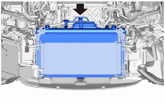
Install the FC radiator assembly to the vehicle.
Note
During install, make sure not to damage the radiator assembly or FC radiator assembly.
-
Using the 6 bolts, install the radiator support sub-assembly and No. 2 radiator support sub-assembly together with the radiator assembly and cooler condenser assembly, as a single unit, to the FC radiator assembly.
- Torque:
- 7.0 N*m { 71 kgf*cm, 62 in.*lbf }
-
Engage the clamp to connect the wire harness to the fan shroud.
-
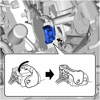
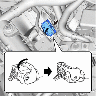
Connect the cooling fan with controller motor. (for No. 2 Fan Side)
-
Connect the cooling fan with controller motor connector and lock them with the lever.
Note
-
When connecting the cooling fan with controller motor connector, make sure that dirt, water or other foreign matter does not contact the connecting parts of the cooling fan with controller motor connector.
-
Be sure to securely connect the cooling fan with controller motor connector.
-
-
-
Connect the cooling fan with controller motor. (for Fan Side)
-
Connect the cooling fan with controller motor connector and lock them with the lever.
Note
-
When connecting the cooling fan with controller motor connector, make sure that dirt, water or other foreign matter does not contact the connecting parts of the cooling fan with controller motor connector.
-
Be sure to securely connect the cooling fan with controller motor connector.
-
-
-
-
INSTALL UPPER RADIATOR SUPPORT SUB-ASSEMBLY
-
Engage the clamp to connect the hood lock control cable assembly.
-
Engage the guide and connect the hood lock control cable assembly.
-
Install the upper radiator support sub-assembly to the vehicle with the 5 bolts.
- Torque:
- 12.5 N*m { 127 kgf*cm, 9 ft.*lbf }
-
Engage the 2 clamps to connect the hood courtesy switch connector (hood lock assembly).
-
Connect the high pitched horn assembly connector.
-
Connect the low pitched horn assembly connector.
-
Connect the thermistor assembly connector.
-
-
CONNECT FC SUB-RADIATOR INLET HOSE
-
To prevent contamination by foreign matter or water droplets, remove the plastic bags from the connecting portions of the FC sub-radiator inlet hose and FC radiator assembly immediately before performing the procedure.
-
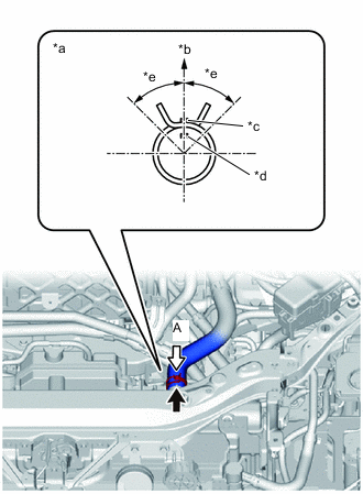
*a View A *b Top of Vehicle *c FC Radiator Assembly Rib *d Hose Paint Mark (White) *e Claw should be within this range (45°) Connect the FC sub-radiator inlet hose to the FC radiator assembly and slide the hose clip to secure it.
Note
Align the hose and the hose clip at the locations shown in the illustration and install them.
Tech Tips
When connecting, if it is difficult to insert the FC sub-radiator inlet hose, coat it with new coolant (Toyota genuine FC stack coolant).
-
-
INSTALL NO. 1 FC RADIATOR OUTLET HOSE
-
To prevent contamination by foreign matter or water droplets, remove the plastic bags from the connecting portions of the No. 1 FC radiator outlet hose and FC radiator pipe immediately before performing the procedure.
-
Connect the No. 1 FC radiator outlet hose to the FC radiator pipe and slide the hose clip to secure it.
Tech Tips
When connecting, if it is difficult to insert the No. 1 FC radiator outlet hose, coat it with new coolant (Toyota genuine FC stack coolant).
-
-
CONNECT FC RADIATOR INLET HOSE
-
To prevent contamination by foreign matter or water droplets, remove the plastic bags from the connecting portions of the FC radiator inlet hose and FC radiator pipe immediately before performing the procedure.
-
*a View A *b Top of Vehicle *c FC Radiator Assembly Rib *d Hose Paint Mark (Yellow) *e Claw should be within this range (45°) Connect the FC radiator inlet hose to the FC radiator pipe and slide the hose clip to secure it.
Note
Align the hose and the hose clip at the locations shown in the illustration and install them.
Tech Tips
When connecting, if it is difficult to insert the FC radiator inlet hose, coat it with new coolant (Toyota genuine FC stack coolant).
-
-
INSTALL NO. 1 RADIATOR AIR GUIDE LH
-
Engage the guide and install a new No. 1 radiator air guide LH to the vehicle.
-
Engage the 2 claws.
-
-
INSTALL NO. 1 RADIATOR AIR GUIDE RH
-
Engage the guide and install a new No. 1 radiator air guide RH to the vehicle.
-
Engage the 2 claws.
-
-
INSTALL AIR CLEANER WITH ELEMENT ASSEMBLY
-
INSTALL AIR CLEANER HOSE ASSEMBLY
-
INSTALL NO. 1 MOTOR UNDER COVER
-
INSTALL AIR CLEANER INLET
-
INSTALL MILLIMETER WAVE RADAR SENSOR ASSEMBLY
-
INSTALL FRONT BUMPER REINFORCEMENT SUB-ASSEMBLY
-
INSTALL FRONT BUMPER ENERGY ABSORBER
-
INSTALL HEADLAMP ASSEMBLY LH
-
INSTALL HEADLAMP ASSEMBLY RH
Tech Tips
Use the same procedure as for the LH side.
-
CONNECT CABLE FROM NEGATIVE AUXILIARY BATTERY TERMINAL
-
INSTALL LUGGAGE TRIM SERVICE HOLE COVER
-
ADD COOLANT (FC STACK COOLANT)
-
INSPECT FOR COOLANT (FC STACK COOLANT) LEAK
-
INSTALL SUSPENSION MEMBER TO FRONT CROSSMEMBER BRACE SUB-ASSEMBLY
-
INSTALL FRONT FLOOR COVER RH
-
INSTALL FRONT FLOOR COVER LH
-
INSTALL NO. 2 MOTOR UNDER COVER
-
INSTALL FRONT BUMPER LOWER ABSORBER