ROTARY VALVE INSTALLATION
PROCEDURE
-
INSTALL FC COOLING WATER TEMPERATURE CONTROL VALVE
-
Install the FC cooling water temperature control valve to the FC cooling water valve bracket with the 3 nuts.
- Torque:
- 5.5 N*m { 56 kgf*cm, 49 in.*lbf }
Note
If the FC cooling water temperature control valve has been struck or dropped, replace it.
-
To prevent contamination by foreign matter or water droplets, remove the plastic bags from the connecting portions of the No. 1 FC cooling by-pass hose and FC cooling water temperature control valve immediately before performing the procedure.
-
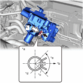
*a View A *b Rear Side of FC Cooling Water Temperature Control Valve *c FC Cooling Water Temperature Control Valve Rib *d Hose Paint Mark (White) *e Claw should be within this range (90°) Connect the No. 1 FC cooling bypass hose to the FC cooling water temperature control valve, secure it with the hose clip, and install the FC cooling water temperature control valve together with the FC cooling water valve bracket.
Note
-
Align the hose and the hose clip at the locations shown in the illustration and install them.
-
For the position of the hose clip, after the FC cooling water temperature control valve is installed, it is at the rear side of the vehicle.
Tech Tips
When connecting, if it is difficult to insert the No. 1 FC cooling by-pass hose, coat it with new coolant (Toyota genuine FC stack coolant).
-
-
To prevent contamination by foreign matter or water droplets, remove the plastic bags from the connecting portions of the No. 1 FC cooling water valve inlet hose and FC cooling water temperature control valve immediately before performing the procedure.
-
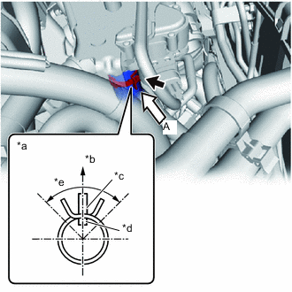
*a View A *b Rear of Vehicle *c FC Cooling Water Temperature Control Valve Rib *d Hose Paint Mark (Yellow) *e Claw should be within this range (90°) Connect the No. 1 FC cooling water valve inlet hose to the FC cooling water temperature control valve and slide the hose clip to secure it.
Note
Align the hose and the hose clip at the locations shown in the illustration and install them.
Tech Tips
When connecting, if it is difficult to insert the No. 1 FC cooling water valve inlet hose, coat it with new coolant (Toyota genuine FC stack coolant).
-
To prevent contamination by foreign matter or water droplets, remove the plastic bags from the connecting portions of the No. 1 FC cooling water valve outlet hose and FC cooling water temperature control valve immediately before performing the procedure.
-
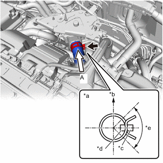
*a View A *b Top of Vehicle *c FC Cooling Water Temperature Control Valve Rib *d Hose Paint Mark (White) *e Claw should be within this range (90°) Connect the No. 1 FC cooling water valve outlet hose to the FC cooling water temperature control valve and slide the hose clip to secure it.
Note
Align the hose and the hose clip at the locations shown in the illustration and install them.
Tech Tips
When connecting, if it is difficult to insert the No. 1 FC cooling water valve outlet hose, coat it with new coolant (Toyota genuine FC stack coolant).
-
Temporarily install the bolt and 2 nuts.
-
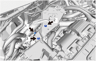
Fully tighten the bolt and 2 nuts in the sequence shown in the illustration.
- Torque:
- 13 N*m { 133 kgf*cm, 10 ft.*lbf }
Note
When tightening, press the FC cooling water valve bracket against each clamping surface of the electric heater sub-assembly bracket when performing the work.
-
Engage the clamp to connect the FC converter power outlet cable to the FC cooling water valve bracket.
-
Engage the 3 clamps to install the No. 2 motor wire to the FC cooling water valve bracket.
-
Connect the FC cooling water temperature control valve connector.
-
Connect the electric heater sub-assembly connector.
-
Engage the clamp to connect the No. 2 motor wire to the inverter terminal cover.
-
Connect the 2 connectors.
-
-
ADD COOLANT (FC STACK COOLANT)
-
INSPECT FOR COOLANT (FC STACK COOLANT) LEAK
-
INSTALL INVERTER COVER
-
INSTALL OUTER COWL TOP PANEL SUB-ASSEMBLY (for LHD)
-
INSTALL OUTER COWL TOP PANEL SUB-ASSEMBLY (for RHD)
-
INSTALL COWL BODY MOUNTING REINFORCEMENT RH (for LHD)
-
INSTALL COWL BODY MOUNTING REINFORCEMENT RH (for RHD)
-
INSTALL WATER GUARD PLATE LH (for LHD)
-
INSTALL WATER GUARD PLATE RH (for RHD)
-
INSTALL NO. 2 HEATER AIR DUCT SPLASH SHIELD SEAL (for LHD)
-
INSTALL NO. 1 HEATER AIR DUCT SPLASH SHIELD SEAL (for RHD)
-
INSTALL WINDSHIELD WIPER MOTOR AND LINK
-
INSTALL SUSPENSION MEMBER TO FRONT CROSSMEMBER BRACE SUB-ASSEMBLY
-
INSTALL FRONT FLOOR COVER RH
-
INSTALL FRONT FLOOR COVER LH
-
INSTALL NO. 2 MOTOR UNDER COVER
-
INSTALL FRONT BUMPER LOWER ABSORBER