ROTARY VALVE REMOVAL
PROCEDURE
-
PRECAUTION
Note
-
The coolant (Toyota genuine FC stack coolant) is an exclusive coolant.
-
The coolant (Toyota genuine FC stack coolant) cannot be reused, so when filling, be sure to fill with new coolant (Toyota genuine FC stack coolant).
-
To prevent degradation of coolant (Toyota genuine FC stack coolant) performance, do not add or fill any other substances such as tap water or battery electrolyte refill liquid.
-
Do not use cotton work gloves or other gloves that could shed fibers.
-
DO NOT use any container that has previously been used to fill substances such as oil.
-
To prevent foreign matter from contaminating the coolant (Toyota genuine FC stack coolant) passages, wash out the prepared container with tap water, then wipe away any water remaining inside the container before using it.
-
If the coolant (Toyota genuine FC stack coolant) passages are filled incorrectly, follow the countermeasures according to "Countermeasures when coolant (Toyota genuine FC stack coolant) passages are filled incorrectly".
-
When the vehicle is parked with the power switch off, if the FC control ECU judges that the FC stack temperature will go below 0°C (32°F), it activates the FC air compressor, hydrogen pump and FC cooling water pump for a maximum of 180 seconds and drains water from the FC stack assembly. When performing inspection or repairs with the power switch off (not on (IG) or on (READY)), disconnect the cable from the negative (-) auxiliary battery terminal before performing work.
-
-
REMOVE FRONT BUMPER LOWER ABSORBER
-
REMOVE NO. 2 MOTOR UNDER COVER
-
REMOVE FRONT FLOOR COVER LH
-
REMOVE FRONT FLOOR COVER RH
-
REMOVE SUSPENSION MEMBER TO FRONT CROSSMEMBER BRACE SUB-ASSEMBLY
-
DRAIN COOLANT (FC STACK COOLANT)
-
REMOVE WINDSHIELD WIPER MOTOR AND LINK
-
REMOVE NO. 2 HEATER AIR DUCT SPLASH SHIELD SEAL (for LHD)
-
REMOVE NO. 1 HEATER AIR DUCT SPLASH SHIELD SEAL (for RHD)
-
REMOVE WATER GUARD PLATE LH (for LHD)
-
REMOVE WATER GUARD PLATE RH (for RHD)
-
REMOVE COWL BODY MOUNTING REINFORCEMENT RH (for LHD)
-
REMOVE COWL BODY MOUNTING REINFORCEMENT RH (for RHD)
-
REMOVE OUTER COWL TOP PANEL SUB-ASSEMBLY (for LHD)
-
REMOVE OUTER COWL TOP PANEL SUB-ASSEMBLY (for RHD)
-
REMOVE INVERTER COVER
-
REMOVE FC COOLING WATER TEMPERATURE CONTROL VALVE
-
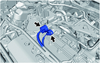
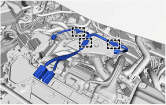
Disconnect the 2 connectors.
-
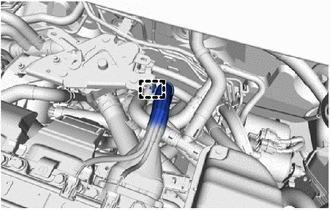
Disengage the clamp to disconnect the No. 2 motor wire from the inverter terminal cover.
-
Disconnect the electric heater sub-assembly connector.
-
Disconnect the FC cooling water temperature control valve connector.
-
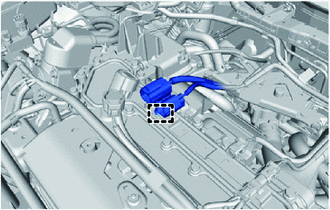
Disengage the 3 clamps to remove the No. 2 motor wire from the FC cooling water valve bracket.
-
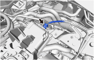
Disengage the clamp to separate the FC converter power outlet cable from the FC cooling water valve bracket.
-
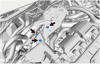
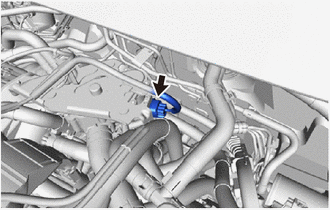
Remove the bolt and 2 nuts.
-
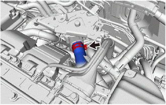
Slide the hose clip and disconnect the No. 1 FC cooling water valve outlet hose from the FC cooling water temperature control valve.
Note
-
When disconnecting, be careful not to damage the hose interior surface or port of FC cooling water temperature control valve portion.
-
Perform the work by hand. Do not use tools.
-
-
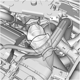
*a Plastic Bag To prevent contamination by foreign matter, cover the connecting portions of the No. 1 FC cooling water valve outlet hose and FC cooling water temperature control valve with plastic bags.
-
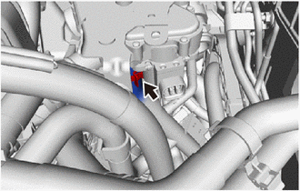
Slide the hose clip and disconnect the No. 1 FC cooling water valve inlet hose from the FC cooling water temperature control valve.
Note
-
When disconnecting, be careful not to damage the hose interior surface or port of FC cooling water temperature control valve portion.
-
Perform the work by hand. Do not use tools.
-
-
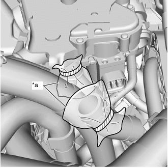
*a Plastic Bag To prevent contamination by foreign matter, cover the connecting portions of the No. 1 FC cooling water valve inlet hose and FC cooling water temperature control valve with plastic bags.
-
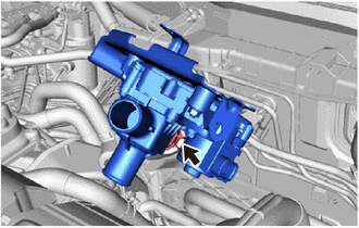
Slide the hose clip, separate the No. 1 FC cooling bypass hose from the FC cooling water temperature control valve, and remove the FC cooling water temperature control valve together with the FC cooling water valve bracket.
Note
-
When disconnecting, be careful not to damage the hose interior surface or port of FC cooling water temperature control valve portion.
-
Perform the work by hand. Do not use tools.
-
If the FC cooling water temperature control valve has been struck or dropped, replace it.
-
-
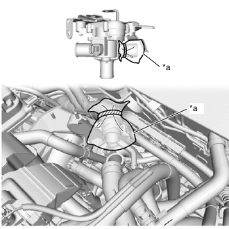
*a Plastic Bag To prevent contamination by foreign matter, cover the connecting portions of the No. 1 FC cooling by-pass hose and FC cooling water temperature control valve with plastic bags.
-
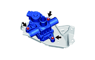
Remove the 3 nuts and FC cooling water temperature control valve from the FC cooling water valve bracket.
Note
If the FC cooling water temperature control valve has been struck or dropped, replace it.
-