WATER PUMP INSTALLATION
PROCEDURE
-
INSTALL STUD BOLT
Tech Tips
Only perform this procedure when replacement of the stud bolt is necessary.
-
Using "TORX" socket wrench E8, install the 2 stud bolts.
- Torque:
- 10 N*m { 102 kgf*cm, 7 ft.*lbf }
-
-
INSTALL FC COOLING WATER PUMP ASSEMBLY
-
Temporarily install the FC cooling water pump assembly to the FC air compressor with motor assembly with the bolt and 2 nuts.
Note
-
When installing, do not hold the FC cooling water pump assembly by its port portion.
-
If the FC cooling water pump assembly has been struck or dropped, replace it.
-
-
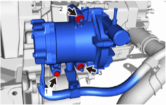
Fully tighten the bolt and 2 nuts in the sequence shown in the illustration.
- Torque:
- 24.5 N*m { 250 kgf*cm, 18 ft.*lbf }
-
Engage the clamp to connect the wire harness to the No. 1 FC air compressor outlet pipe.
-
-
INSTALL NO. 3 FC AIR COMPRESSOR OUTLET PIPE BRACKET
-
Install the No. 3 FC air compressor outlet pipe bracket to the FC air compressor with motor assembly with the 2 bolts.
- Torque:
- 19.5 N*m { 199 kgf*cm, 14 ft.*lbf }
-
Install the 2 bolts.
- Torque:
- 8.0 N*m { 82 kgf*cm, 71 in.*lbf }
-
-
INSTALL FC COOLING WATER PUMP INLET HOSE
-
To prevent contamination by foreign matter or water droplets, remove the plastic bags from the connecting portions of the FC cooling water pump inlet hose and FC cooling water pump assembly immediately before performing the procedure.
-
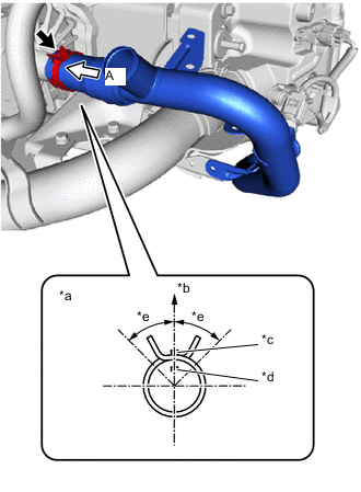
*a View A *b Top of Vehicle *c FC Cooling Water Pump Assembly Rib *d Hose Paint Mark (Yellow) *e Claw should be within this range (45°) Connect the FC cooling water pump inlet hose to the FC cooling water pump assembly and slide the hose clip to secure it.
Note
Align the hose and the hose clip at the locations shown in the illustration and install them.
Tech Tips
When connecting, if it is difficult to insert the FC cooling water pump inlet hose, coat it with new coolant (Toyota genuine FC stack coolant).
-
Connect the FC cooling water pump inlet pipe with the 2 bolts.
- Torque:
- 8.0 N*m { 82 kgf*cm, 71 in.*lbf }
-
Connect the water temperature sensor connector.
-
-
INSTALL NO. 1 FC COOLING WATER PUMP OUTLET HOSE
-
To prevent contamination by foreign matter or water droplets, remove the plastic bags from the connecting portions of the No. 1 FC cooling water pump outlet hose and FC cooling water pump assembly immediately before performing the procedure.
-
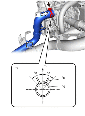
*a View A *b Top of Vehicle *c FC Cooling Water Pump Assembly Rib *d Hose Paint Mark (White) *e Claw should be within this range (45°) Connect the No. 1 FC cooling water pump outlet hose to the FC cooling water pump assembly and slide the hose clip to secure it.
Note
Align the hose and the hose clip at the locations shown in the illustration and install them.
Tech Tips
When connecting, if it is difficult to insert the No. 1 FC cooling water pump outlet hose, coat it with new coolant (Toyota genuine FC stack coolant).
-
Engage the clamp to connect the No. 2 FC cooling water pump outlet hose.
-
-
CONNECT INTERCOOLER COOLING WATER INLET HOSE
-
To prevent contamination by foreign matter or water droplets, remove the plastic bags from the connecting portions of the intercooler cooling water inlet hose and FC cooling water pump outlet pipe immediately before performing the procedure.
-
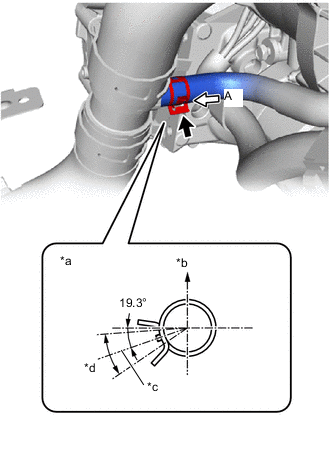
*a View A *b Top of Vehicle *c Hose Clip Center Position *d Claw should be within this range (30°) Connect the intercooler cooling water inlet hose to the FC cooling water pump outlet pipe and slide the hose clip to secure it.
Note
Align the hose and the hose clip at the locations shown in the illustration and install them.
Tech Tips
When connecting, if it is difficult to insert the intercooler cooling water inlet hose, coat it with new coolant (Toyota genuine FC stack coolant).
-
Engage the 2 clamps to connect the intercooler cooling water inlet hose to the No. 3 FC air compressor outlet pipe bracket and FC cooling water pump inlet pipe.
-
-
CONNECT FC CONVERTER COOLING WATER OUTLET HOSE
-
Engage the clamp to connect the FC converter cooling water outlet hose to the No. 3 FC air compressor outlet pipe bracket.
-
-
CONNECT INTERCOOLER COOLING WATER OUTLET HOSE
-
Engage the 2 clamps to connect the intercooler cooling water outlet hose to the No. 3 FC air compressor outlet pipe bracket and FC cooling water pump inlet pipe.
-
-
INSTALL FC WATER PUMP DRAIN HOSE ASSEMBLY
-
To prevent contamination by foreign matter or water droplets, remove the plastic bags from the connecting portions of the FC water pump drain hose assembly and FC cooling water pump assembly immediately before performing the procedure.
-
Install the FC water pump drain hose assembly to the FC cooling water pump assembly and slide the hose clip to secure it.
Tech Tips
When installing, if it is difficult to insert the FC water pump drain hose assembly, coat it with new coolant (Toyota genuine FC stack coolant).
-
-
INSTALL FC AIR COMPRESSOR WITH MOTOR ASSEMBLY
-
ADD COOLANT (FC STACK COOLANT)
-
INSPECT FOR COOLANT (FC STACK COOLANT) LEAK
-
INSTALL SUSPENSION MEMBER TO FRONT CROSSMEMBER BRACE SUB-ASSEMBLY
-
INSTALL FRONT FLOOR COVER RH
-
INSTALL FRONT FLOOR COVER LH
-
INSTALL NO. 2 MOTOR UNDER COVER
-
INSTALL FRONT BUMPER LOWER ABSORBER