COOLANT REPLACEMENT
PROCEDURE
-
PRECAUTION
Note
-
The coolant (Toyota genuine FC stack coolant) is an exclusive coolant.
-
The coolant (Toyota genuine FC stack coolant) cannot be reused, so when filling, be sure to fill with new coolant (Toyota genuine FC stack coolant).
-
To prevent degradation of coolant (Toyota genuine FC stack coolant) performance, do not add or fill any other substances such as tap water or battery electrolyte refill liquid.
-
Do not use cotton work gloves or other gloves that could shed fibers.
-
DO NOT use any container that has previously been used to fill substances such as oil.
-
To prevent foreign matter from contaminating the coolant (Toyota genuine FC stack coolant) passages, wash out the prepared container with tap water, then wipe away any water remaining inside the container before using it.
-
If the coolant (Toyota genuine FC stack coolant) passages are filled incorrectly, follow the countermeasures according to "Countermeasures when coolant (Toyota genuine FC stack coolant) passages are filled incorrectly".
-
When the vehicle is parked with the power switch off, if the FC control ECU judges that the FC stack temperature will go below 0°C (32°F), it activates the FC air compressor, hydrogen pump and FC cooling water pump for a maximum of 180 seconds and drains water from the FC stack assembly. When performing inspection or repairs with the power switch off (not on (IG) or on (READY)), disconnect the cable from the negative (-) auxiliary battery terminal before performing work.
-
-
REMOVE FRONT BUMPER LOWER ABSORBER
-
REMOVE NO. 2 MOTOR UNDER COVER
-
REMOVE FRONT FLOOR COVER LH
-
REMOVE FRONT FLOOR COVER RH
-
REMOVE SUSPENSION MEMBER TO FRONT CROSSMEMBER BRACE SUB-ASSEMBLY
-
DRAIN COOLANT (FC STACK COOLANT)
CAUTION:
-
When the coolant (Toyota genuine FC stack coolant) temperature is high, do not remove the radiator cap sub-assembly or the drain cock plug of the FC radiator, and do not disconnect the No. 2 FC cooling water pump outlet hose or No. 2 FC cooling water valve inlet hose.
-
Fluid and steam may spray out due to high pressure, possibly resulting in burns.
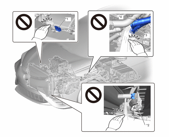
*1 Radiator Cap Sub-assembly *2 FC Radiator Drain Cock Plug *3 No. 2 FC Cooling Water Pump Outlet Hose *4 No. 2 FC Cooling Water Valve Inlet Hose Note
Collect the removed coolant (Toyota genuine FC stack coolant) and measure the amount, then check that the same amount or greater has been added when coolant is refilled.
-
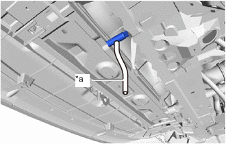
*a HOSE Connect a hose with an inside diameter of 9 mm (0.354 in.) to the FC radiator assembly drain cock as shown in the illustration.
-
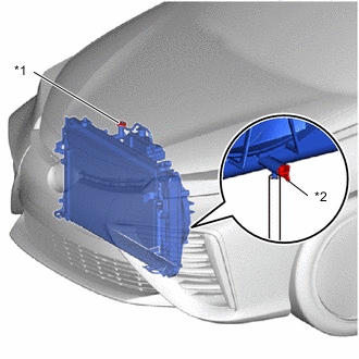
*1 Radiator Cap Sub-assembly *2 FC Radiator Drain Cock Plug Loosen the FC radiator assembly drain cock plug.
-
Remove the radiator cap sub-assembly, then drain the coolant (Toyota genuine FC stack coolant).
Note
In order to measure the volume of drained coolant (Toyota genuine FC stack coolant), make sure to recover the coolant.
-
Tighten the FC radiator assembly drain cock plug by hand.
-
Remove the hose from the FC radiator assembly drain cock.
-
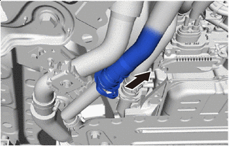
Disconnect the No. 2 FC cooling water valve inlet hose (with FC water hose connector).
Note
Before disconnecting the No. 2 FC cooling water valve inlet hose, check that there is no mud or other contaminant on the No. 2 FC cooling water valve inlet hose or FC stack cooling water outlet pipe, and clean as necessary.
-
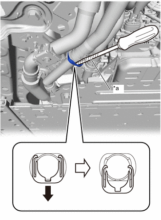
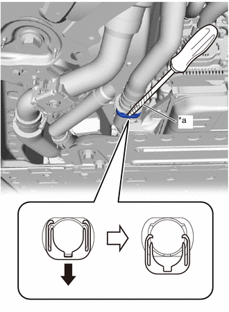
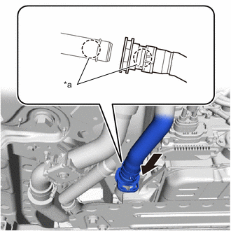
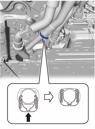
*a Protective Tape 
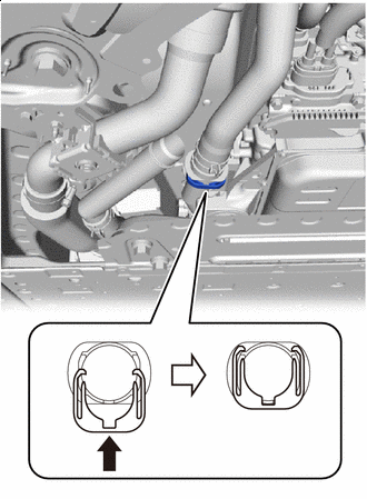
Press Down Using a screwdriver with its tip wrapped in protective tape, press down the retainer of the FC water hose connector to release the lock.
-
Disconnect Slowly Separate the No. 2 FC cooling water valve inlet hose (with FC water hose connector) from the FC stack cooling water outlet pipe, and drain the coolant (Toyota genuine FC stack coolant).
Note
-
In order to measure the volume of drained coolant (Toyota genuine FC stack coolant), make sure to recover the coolant.
-
Disconnect the components slowly to prevent coolant (Toyota genuine FC stack coolant) from splattering.
-
Perform the procedures by hand. Do not use any tools.
-
Do not rotate or tilt the No. 2 FC cooling water valve inlet hose (with FC water hose connector) when pulling it out.
-
If the O-ring on the inner side of the FC water hose connector is damaged or falls out, replace the FC water hose connector with a new one.
-
-
After the No. 2 FC cooling water valve inlet hose (with FC water hose connector) has been disconnected, check that there is no mud or other contaminant adhering to the sealing surface of the FC stack cooling water outlet pipe, and clean it as necessary.
-
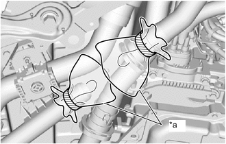
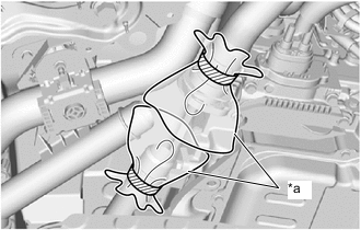
*a Plastic Bag When working with the No. 2 FC cooling water valve inlet hose (with FC water hose connector) disconnected, to prevent foreign matter from entering, protect the connecting portions of the No. 2 FC cooling water valve inlet hose (with FC water hose connector) and FC stack cooling water outlet pipe with plastic bags.
-
-
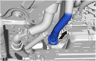
Disconnect the No. 2 FC cooling water pump outlet hose (with FC water hose connector).
Note
Before disconnecting the No. 2 FC cooling water pump outlet hose, check that there is no mud or other contaminant on the No. 2 FC cooling water pump outlet hose or FC stack cooling water inlet pipe, and clean as necessary.
-
*a Protective Tape Press Down Using a screwdriver with its tip wrapped in protective tape, press down the retainer of the FC water hose connector to release the lock.
-
Disconnect Slowly Separate the No. 2 FC cooling water pump outlet hose (with FC water hose connector) from the FC stack cooling water inlet pipe, and drain the coolant (Toyota genuine FC stack coolant).
Note
-
In order to measure the volume of drained coolant (Toyota genuine FC stack coolant), make sure to recover the coolant.
-
Disconnect the components slowly to prevent coolant (Toyota genuine FC stack coolant) from splattering.
-
Perform the work by hand. Do not use tools.
-
Do not rotate or tilt the No. 2 FC cooling water pump outlet hose (with FC water hose connector) when pulling it out.
-
If the O-ring on the inner side of the FC water hose connector is damaged or falls out, replace the FC water hose connector with a new one.
-
-
After the No. 2 FC cooling water pump outlet hose (with FC water hose connector) has been disconnected, check that there is no mud or other contaminant adhering to the sealing surface of the FC stack cooling water inlet pipe, and clean it as necessary.
-
*a Plastic Bag When working with the No. 2 FC cooling water pump outlet hose (with FC water hose connector) disconnected, to prevent foreign matter from entering, protect the connecting portions of the No. 2 FC cooling water pump outlet hose (with FC water hose connector) and FC stack cooling water inlet pipe with plastic bags.
-
-
Connect the No. 2 FC cooling water pump outlet hose (with FC water hose connector).
-
After working with the No. 2 FC cooling water pump outlet hose (with FC water hose connector) disconnected, remove the plastic bags that are protecting the connecting portions of the No. 2 FC cooling water pump outlet hose (with FC water hose connector) and FC stack cooling water inlet pipe.
-
*a No Identification Markings Slowly Insert Line up the No. 2 FC cooling water pump outlet hose (with FC water hose connector) and FC stack cooling water inlet pipe in a row, and push them in as a single unit.
Note
-
The No. 2 FC cooling water pump outlet hose (with FC water hose connector) and FC stack cooling water inlet pipe do not have identification markings.
-
If the O-ring on the inner side of the FC water hose connector is damaged or falls out, replace the FC water hose connector with a new one.
-
Do not rotate or tilt the No. 2 FC cooling water pump outlet hose (with FC water hose connector) when pushing it in.
-
Securely and fully insert the No. 2 FC cooling water pump outlet hose (with FC water hose connector) all the way into the FC stack cooling water inlet pipe.
-
-
Push Up Push up the retainer of the FC water hose connector and lock it.
Tech Tips
The retainer of the FC water hose connector is designed so that it cannot be locked if the No. 2 FC cooling water pump outlet hose (with FC water hose connector) is not securely inserted into the FC stack cooling water inlet pipe.
-
After connecting the No. 2 FC cooling water pump outlet hose (with FC water hose connector), firmly pull on the FC water hose connector and FC stack cooling water inlet pipe to check that they are securely connected.
-
-
Connect the No. 2 FC cooling water valve inlet hose (with FC water hose connector).
-
After working with the No. 2 FC cooling water valve inlet hose (with FC water hose connector) disconnected, remove the plastic bags that are protecting the connecting portions of the No. 2 FC cooling water valve inlet hose (with FC water hose connector) and FC stack cooling water outlet pipe.
-
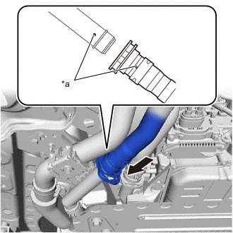
*a Identification Markings (White) Slowly Insert Line up the No. 2 FC cooling water valve inlet hose (with FC water hose connector) and FC stack cooling water outlet pipe in a row, and push them in as a single unit.
Note
-
Align the white identification markings of the No. 2 FC cooling water valve inlet hose (with FC water hose connector) and the FC stack cooling water outlet pipe.
-
If the O-ring on the inner side of the FC water hose connector is damaged or falls out, replace the FC water hose connector with a new one.
-
Do not rotate or tilt the No. 2 FC cooling water valve inlet hose (with FC water hose connector) when pushing it in.
-
Securely and fully insert the No. 2 FC cooling water valve inlet hose (with FC water hose connector) all the way into the FC stack cooling water outlet pipe.
-
-
Push Up Push up the retainer of the FC water hose connector and lock it.
Tech Tips
The retainer of the FC water hose connector is designed so that it cannot be locked if the No. 2 FC cooling water valve inlet hose (with FC water hose connector) is not securely inserted into the FC stack cooling water outlet pipe.
-
After connecting the No. 2 FC cooling water valve inlet hose (with FC water hose connector), firmly pull on the FC water hose connector and FC stack cooling water outlet pipe to check that they are securely connected.
-
-
-
ADD COOLANT (FC STACK COOLANT)
Note
-
Make sure to use the GTS to perform air bleeding of the coolant (Toyota genuine FC stack coolant) passages.
-
If air bleeding is performed without using the Techstream, the air bleeding of the coolant (Toyota genuine FC stack coolant) passages may be incomplete.
-
If the vehicle is driven while the coolant (Toyota genuine FC stack coolant) system is contaminated with air, the following DTC may be stored.
DTC No. Detection Item P1DE4-450 FC Coolant Water Temperature Malfunction
Tech Tips
The coolant (Toyota genuine FC stack coolant) capacity: 19.6 liters (20.7 US qts, 17.2 Imp. qts)
-
Connect the GTS to the DLC3.
-
Turn the power switch on (IG).
-
Turn the GTS on.
-
Enter the following menus: Powertrain / FC / Utility / FC Stack Coolant Air Bleeding
Powertrain > FC > UtilityTester Display FC Stack Coolant Air Bleeding -
Following the instructions on the GTS, perform air bleeding of the coolant (Toyota genuine FC stack coolant) passages.
Tech Tips
-
When using 2-part type coolant (Toyota genuine FC stack coolant and Toyota genuine FC stack coolant dilution water), mix the two liquids in a 1:1 ratio before using them.
-
The FC cooling water air bleeding valve and heater air bleeding valve that appear in the procedures for air bleeding of the coolant (Toyota genuine FC stack coolant) passages can be found at the locations shown in the illustration.
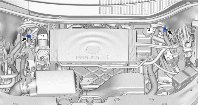
*1 FC Cooling Water Air-bleeding Valve *2 Heater Air-bleeding Valve
-
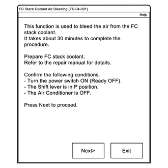
Proceed to the screen shown in the illustration, and begin air bleeding of the coolant (Toyota genuine FC stack coolant) passages.
Tech Tips
Coolant (Toyota genuine FC stack coolant) filling is performed multiple times during the air bleeding procedure.
-
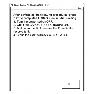
When the screen shown in the illustration is displayed, the air bleeding procedure for the coolant (Toyota genuine FC stack coolant) passages is complete.
-
-
-
INSPECT FOR COOLANT (FC STACK COOLANT) LEAK
-
INSTALL SUSPENSION MEMBER TO FRONT CROSSMEMBER BRACE SUB-ASSEMBLY
-
INSTALL FRONT FLOOR COVER RH
-
INSTALL FRONT FLOOR COVER LH
-
INSTALL NO. 2 MOTOR UNDER COVER
-
INSTALL FRONT BUMPER LOWER ABSORBER