COOLING FAN SYSTEM Cooling Fan Circuit
DESCRIPTION
For the cooling fan, the FC control ECU calculates the fan speed needed for cooling based on the FC stack assembly coolant temperature, A/C switch, air conditioner refrigerant pressure and vehicle speed information, and sends a control signal to the cooling fan with controller motor. Based on the duty ratio in the signal from the FC control ECU, the continuously variable speed of the cooling fan with controller motor is controlled. In response to driving conditions, the FC control ECU sends a signal to the cooling fan with controller motor to control fan speed to the optimal level, achieving a balance between cooling performance and silent operation.
WIRING DIAGRAM
CAUTION / NOTICE / HINT
Note
Inspect the fuses for circuits related to this system before performing the following procedure.
PROCEDURE
-
PERFORM ACTIVE TEST USING TECHSTREAM (Radiator Fan 1)
-
Connect the GTS to the DLC3.
-
Turn the power switch on (IG).
-
Enter the following menus: Powertrain / FC / Active Test / Radiator Fan 1.
Powertrain > FC > Active TestTester Display Radiator Fan1 -
Check the operation of the fan while operating them using the GTS.
OK Tester Operation Fan Operation ON Cooling fan operate OFF Cooling fan stop Result Result Proceed to OK A NG (Fan does not operate) B NG (Fan does not stop) C
B 
CHECK HARNESS AND CONNECTOR (POWER SOURCE) Click here
C
CHECK HARNESS AND CONNECTOR (FC CONTROL ECU - COOLING FAN WITH CONTROLLER MOTOR (for Fan Side)) Click here
A 
-
-
PERFORM ACTIVE TEST USING TECHSTREAM (Radiator Fan 2)
-
Connect the GTS to the DLC3.
-
Turn the power switch on (IG).
-
Enter the following menus: Powertrain / FC / Active Test / Radiator Fan 2.
Powertrain > FC > Active TestTester Display Radiator Fan2 -
Check the operation of the fan while operating them using the GTS.
OK Tester Operation Fan Operation ON Cooling fan operate OFF Cooling fan stop Result Result Proceed to OK A NG (Fan does not operate) B NG (Fan does not stop) C
A 
GO TO PROBLEM SYMPTOMS TABLE
B
CHECK HARNESS AND CONNECTOR (POWER SOURCE) Click here
C
CHECK HARNESS AND CONNECTOR (FC CONTROL ECU - COOLING FAN WITH CONTROLLER MOTOR (for No. 2 Fan Side)) Click here
-
-
CHECK HARNESS AND CONNECTOR (POWER SOURCE)
-
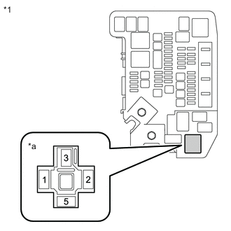
*1 Motor Room Relay Block *a Radiator Fan Relay (RDI FAN NO.1) Holder Remove the radiator fan relay (RDI FAN NO.1) from the motor room relay block.
-
Measure the voltage according to the value(s) in the table below.
Standard Voltage Tester Connection Condition Specified Condition 3 (Radiator fan relay (RDI FAN NO.1) holder) - Body ground Always 11 to 14V -
Install the radiator fan relay (RDI FAN NO.1) to the motor room relay block.
Result Proceed to OK NG
NG
REPAIR OR REPLACE HARNESS AND CONNECTOR (RADIATOR FAN RELAY - BODY GROUND)
OK
-
-
CHECK HARNESS AND CONNECTOR (FC CONTROL ECU - RADIATOR FAN RELAY (RDI FAN NO.1))
-
Disconnect the A48 FC control ECU connector.
-
Remove the radiator fan relay (RDI FAN NO.1) from the motor room relay block.
-
Measure the resistance according to the value(s) in the table below.
Standard Resistance Tester Connection Condition Specified Condition A48-52 (RLFM) - 1 (Radiator fan relay (RDI FAN NO.1)) Always Below 1 Ω A48-52(RLFM) or 1 (Radiator fan relay (RDI FAN NO.1)) - Other terminals or Body ground Always 10 kΩ or higher -
Install the radiator fan relay (RDI FAN NO.1) to the motor room relay block.
-
Connect the A48 FC control ECU connector.
Result Proceed to OK NG
NG
REPAIR OR REPLACE HARNESS AND CONNECTOR (FC CONTROL ECU - RADIATOR FAN RELAY (RDI FAN NO.1))
OK
-
-
CHECK RADIATOR FAN RELAY
Result Proceed to OK NG
NG
REPLACE RADIATOR FAN RELAY
OK
-
CHECK HARNESS AND CONNECTOR (RADIATOR FAN RELAY (RDI FAN NO.1) - BODY GROUNDRADIATOR FAN RELAY (RDI FAN NO.1) - BODY GROUND)
-
Remove the radiator fan relay (RDI FAN NO.1) from the motor room relay block.
-
Measure the resistance according to the value(s) in the table below.
Standard Resistance Tester Connection Condition Specified Condition 2 (Radiator fan relay (RDI FAN NO.1)) - Body ground Always Below 1 Ω -
Install the radiator fan relay (RDI FAN NO.1) to the motor room relay block.
Result Proceed to OK NG
NG
REPAIR OR REPLACE HARNESS AND CONNECTOR (RADIATOR FAN RELAY (RDI FAN NO.1) - BODY GROUND)
OK
-
-
CHECK HARNESS AND CONNECTOR (COOLING FAN WITH CONTROLLER MOTOR (for Fan Side) - RADIATOR FAN RELAY (RDI FAN NO.1))
-
Disconnect the A53 cooling fan with controller motor (for Fan Side).
-
Remove the radiator fan relay (RDI FAN NO.1) from the motor room relay block.
-
Measure the resistance according to the value(s) in the table below.
Standard Resistance Tester Connection Condition Specified Condition A53-3(+B1) - 5 (Radiator fan relay (RDI FAN NO.1)) Always Below 1 Ω A53-3 (+B1) or 5 (Radiator fan relay (RDI FAN NO.1)) - Other terminals or Body ground Always 10 kΩ or higher -
Install the radiator fan relay (RDI FAN NO.1) to the motor room relay block.
-
Connect the A53 cooling fan with controller motor (for Fan Side).
Result Proceed to OK NG
NG
REPAIR OR REPLACE HARNESS AND CONNECTOR (COOLING FAN WITH CONTROLLER MOTOR (for Fan Side) - RADIATOR FAN RELAY (RDI FAN NO.1))
OK
-
-
CHECK HARNESS AND CONNECTOR (COOLING FAN WITH CONTROLLER MOTOR (for Fan Side) - BODY GROUND)
-
Disconnect the A53 cooling fan with controller motor (for Fan Side).
-
Measure the resistance according to the value(s) in the table below.
Standard Resistance Tester Connection Condition Specified Condition A53-3 (E1) - Body ground Always Below 1 Ω -
Connect the A53 cooling fan with controller motor (for Fan Side).
Result Proceed to OK NG
OK
GO TO STEP 15 Click here
NG
REPAIR OR REPLACE HARNESS AND CONNECTOR (COOLING FAN WITH CONTROLLER MOTOR (for Fan Side) - BODY GROUND)
-
-
CHECK HARNESS AND CONNECTOR (POWER SOURCE)
-
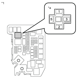
*1 Motor Room Relay Block *a Radiator No. 2 radiator Fan Relay (RDI FAN NO.2) Holder Remove the No. 2 radiator fan relay (RDI FAN NO.2) from the motor room relay block.
-
Measure the voltage according to the value(s) in the table below.
Standard Voltage Tester Connection Condition Specified Condition 3 (No. 2 radiator fan relay (RDI FAN NO.1) holder) - Body ground Always 11 to 14V -
Install the No. 2 radiator fan relay (RDI FAN NO.2) to the motor room relay block.
Result Proceed to OK NG
NG
REPAIR OR REPLACE HARNESS AND CONNECTOR (RADIATOR FAN RELAY - BODY GROUND)
OK
-
-
CHECK HARNESS AND CONNECTOR (FC CONTROL ECU - NO. 2 RADIATOR FAN RELAY (RDI FAN NO.2))
-
Disconnect the A48 FC control ECU connector.
-
Remove the No. 2 radiator fan relay (RDI FAN NO.2) from the motor room relay block.
-
Measure the resistance according to the value(s) in the table below.
Standard Resistance Tester Connection Condition Specified Condition A48-52 (RLFM) - 1 (No. 2 radiator fan relay (RDI FAN NO.2)) Always Below 1 Ω A48-52(RLFM) or 1 (No. 2 radiator fan relay (RDI FAN NO.2)) - Other terminals or Body ground Always 10 kΩ or higher -
Install the No. 2 radiator fan relay (RDI FAN NO.2) to the motor room relay block.
-
Connect the A48 FC control ECU connector.
Result Proceed to OK NG
NG
REPAIR OR REPLACE HARNESS AND CONNECTOR (FC CONTROL ECU - NO. 2 RADIATOR FAN RELAY (RDI FAN NO.2))
OK
-
-
CHECK NO. 2 RADIATOR FAN RELAY
Result Proceed to OK NG
NG
REPLACE RADIATOR FAN RELAY
OK
-
CHECK HARNESS AND CONNECTOR (NO. 2 RADIATOR FAN RELAY (RDI FAN NO.2) - BODY GROUND)
-
Remove the No. 2 radiator fan relay (RDI FAN NO.2) from the motor room relay block.
-
Measure the resistance according to the value(s) in the table below.
Standard Resistance Tester Connection Condition Specified Condition 2 (No. 2 radiator fan relay (RDI FAN NO.2)) - Body ground Always Below 1 Ω -
Install the No. 2 radiator fan relay (RDI FAN NO.2) to the motor room relay block.
Result Proceed to OK NG
NG
REPAIR OR REPLACE HARNESS AND CONNECTOR (NO. 2 RADIATOR FAN RELAY (RDI FAN NO.2) - BODY GROUND)
OK
-
-
CHECK HARNESS AND CONNECTOR (COOLING FAN WITH CONTROLLER MOTOR (for No. 2 Fan Side) - NO. 2 RADIATOR FAN RELAY (RDI FAN NO.2))
-
Disconnect the A54 cooling fan with controller motor (for No. 2 Fan Side).
-
Remove the No. 2 radiator fan relay (RDI FAN NO.2) from the motor room relay block.
-
Measure the resistance according to the value(s) in the table below.
Standard Resistance Tester Connection Condition Specified Condition A54-3(+B2) - 5 (No. 2 radiator fan relay (RDI FAN NO.2)) Always Below 1 Ω A54-3 (+B2) or 5 (No. 2 radiator fan relay (RDI FAN NO.2)) - Other terminals or Body ground Always 10 kΩ or higher -
Install the No. 2 radiator fan relay (RDI FAN NO.2) to the motor room relay block.
-
Connect the A54 cooling fan with controller motor (for No. 2 Fan Side).
Result Proceed to OK NG
NG
REPAIR OR REPLACE HARNESS AND CONNECTOR (COOLING FAN WITH CONTROLLER MOTOR (for No. 2 Fan Side) - NO. 2 RADIATOR FAN RELAY (RDI FAN NO.2))
OK
-
-
CHECK HARNESS AND CONNECTOR (COOLING FAN WITH CONTROLLER MOTOR (for No. 2 Fan Side) - BODY GROUND)
-
Disconnect the A54 cooling fan with controller motor (for No. 2 Fan Side).
-
Measure the resistance according to the value(s) in the table below.
Standard Resistance Tester Connection Condition Specified Condition A54-3 (E2) - Body ground Always Below 1 Ω -
Connect the A54 cooling fan with controller motor (for No. 2 Fan Side).
Result Proceed to OK NG
OK
GO TO STEP 18 Click here
NG
REPAIR OR REPLACE HARNESS AND CONNECTOR (COOLING FAN WITH CONTROLLER MOTOR (for No. 2 Fan Side) - BODY GROUND)
-
-
CHECK HARNESS AND CONNECTOR (FC CONTROL ECU - COOLING FAN WITH CONTROLLER MOTOR (for Fan Side))
-
Disconnect the A48 FC control ECU connector.
-
Disconnect the A53 cooling fan with controller motor (for Fan Side).
-
Measure the resistance according to the value(s) in the table below.
Standard Resistance Tester Connection Condition Specified Condition A48-4 (WFN1) - A53-2 (SI) Always Below 1 Ω A48-4 (WFN1) or A53-2 (SI) - Other terminals or Body ground Always 10 kΩ or higher -
Connect the A53 cooling fan with controller motor (for Fan Side).
-
Connect the A48 FC control ECU connector.
Result Proceed to OK NG
NG
REPAIR OR REPLACE HARNESS AND CONNECTOR (FC CONTROL ECU - COOLING FAN WITH CONTROLLER MOTOR (for Fan Side))
OK
-
-
REPLACE COOLING FAN WITH CONTROLLER MOTOR (for Fan Side)
Result Proceed to Next
Next
-
CONFIRM PROBLEM SYMPTOMS
-
Check whether the problem symptoms have been corrected.
Result Result Proceed to Problem has been corrected. A Problem has not been corrected. B
A
END
B
REPAIR FC CONTROL ECU Click here
-
-
CHECK HARNESS AND CONNECTOR (FC CONTROL ECU - COOLING FAN WITH CONTROLLER MOTOR (for No. 2 Fan Side))
-
Disconnect the A48 FC control ECU connector.
-
Disconnect the A54 cooling fan with controller motor (for No. 2 Fan Side).
-
Measure the resistance according to the value(s) in the table below.
Standard Resistance Tester Connection Condition Specified Condition A48-12 (WFN2) - A54-2 (SI2) Always Below 1 Ω A48-12 (WFN2) or A54-2 (SI2) - Other terminals or Body ground Always 10 kΩ or higher -
Connect the A54 cooling fan with controller motor (for No. 2 Fan Side).
-
Connect the A48 FC control ECU connector.
Result Proceed to OK NG
NG
REPAIR OR REPLACE HARNESS AND CONNECTOR (FC CONTROL ECU - COOLING FAN WITH CONTROLLER MOTOR (for No. 2 Fan Side))
OK
-
-
REPLACE COOLING FAN WITH CONTROLLER MOTOR (for Fan No. 2 Side)
Result Proceed to Next
Next
-
CONFIRM PROBLEM SYMPTOMS
-
Check whether the problem symptoms have been corrected.
Result Result Proceed to Problem has been corrected. A Problem has not been corrected. B
A
END
B
REPAIR FC CONTROL ECU Click here
-