AIR COMPRESSOR INSTALLATION

PROCEDURE
-
INSTALL FC AIR COMPRESSOR BRACKET
-
Install the FC air compressor bracket to the FC air compressor with motor assembly with the 8 bolts.
- Torque:
- 42 N*m { 428 kgf*cm, 31 ft.*lbf }
-
Install the FC air compressor cable to the FC air compressor bracket with the 2 bolts.
- Torque:
- 8.0 N*m { 82 kgf*cm, 71 in.*lbf }
-
-
INSTALL FC AIR COMPRESSOR WITH MOTOR ASSEMBLY
-
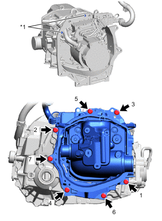
*1 Knock Pin Check that the 2 knock pins of the FC air compressor with motor assembly are not damaged.
-
Using an engine sling device, hang the FC air compressor with motor assembly.
Note
Set the engine sling device so that the FC air compressor with motor assembly is horizontal and level.
-
Align the knock pins with the knock pin holes, and temporarily install the FC air compressor with motor assembly to the FCV transaxle with motor assembly with the 7 bolts.
Note
-
While preventing the motor portion of the FC air compressor with motor assembly from touching the housing of the FCV transaxle with motor assembly, install the FC air compressor with motor assembly.
-
While keeping them straight and level, install the FC air compressor with motor assembly and FCV transaxle with motor assembly.
-
Check that the contact surfaces are fully contacting with no gaps, and then tighten the bolts.
-
-
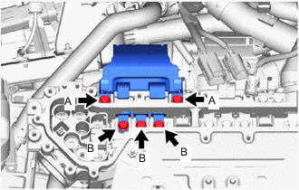
Fully tighten the 7 bolts in the order shown in the illustration.
- Torque:
- 46 N*m { 469 kgf*cm, 34 ft.*lbf }
-
Change the position of the height adjustment attachment to the position used when removing the FCV transaxle with motor assembly, and support the FC air compressor with motor assembly and FCV transaxle with motor assembly.
Note
Using the height adjustment attachment, set the FC air compressor with motor assembly and FCV transaxle with motor assembly so that they are horizontal and level.
-
-
INSTALL FC AIR COMPRESSOR CABLE BRACKET
-
Install the FC air compressor cable bracket to the FCV transaxle with motor assembly with the bolt.
- Torque:
- 8.0 N*m { 82 kgf*cm, 71 in.*lbf }
-
Install the grounding wire to the FC air compressor cable bracket with the bolt.
- Torque:
- 8.4 N*m { 86 kgf*cm, 74 in.*lbf }
-
Engage the clamp to install the FC air compressor cable to the FC air compressor cable bracket.
-
-
INSTALL STUD BOLT
-
INSTALL FC COOLING WATER PUMP ASSEMBLY
-
INSTALL NO. 3 FC AIR COMPRESSOR OUTLET PIPE BRACKET
-
Install the No. 3 FC air compressor outlet pipe bracket to the FC air compressor bracket with the 2 bolts.
- Torque:
- 19.5 N*m { 199 kgf*cm, 14 ft.*lbf }
-
-
INSTALL NO. 1 FC AIR COMPRESSOR OUTLET PIPE
-
To prevent contamination by foreign matter or water droplets, remove the plastic bags from the connecting portions of the No. 1 FC air compressor outlet hose and FC air compressor with motor assembly immediately before performing the procedure.
-
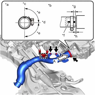
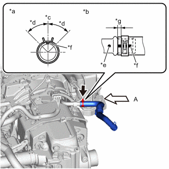
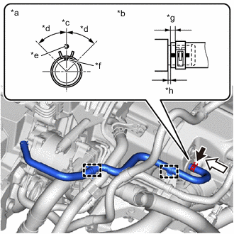
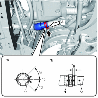
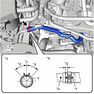
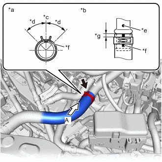
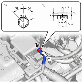
*a View A *b Hose End and Hose Clamp Position *c Upper Side of Vehicle *d Right Side of Vehicle *e Area of Threaded Portion of Hose Clamp: 90° *f Hose Paint Mark (White) *g Distance from Hose End to Hose Clamp: 2 to 5 mm (0.0788 to 0.196 in.) *h Distance from Hose End to Stopper Portion: 0 to 2 mm (0 to 0.0787 in.) Temporarily install the No. 1 FC air compressor outlet hose to the FC air compressor with motor assembly.
Note
Before installing, check that no foreign matter has entered from the connecting portions.
-
Install the No. 1 FC air compressor outlet pipe to the No. 3 FC air compressor outlet pipe bracket with the 2 bolts.
- Torque:
- 8.0 N*m { 82 kgf*cm, 71 in.*lbf }
-
Tighten the hose clamp to secure the No. 1 FC air compressor outlet hose to the FC air compressor with motor assembly.
- Torque:
- 6.3 N*m { 64 kgf*cm, 56 in.*lbf }
Note
Align the hose and hose clamp at the locations shown in the illustration and install them.
-
Engage the clamp to install the FC cooling water pump cable to the No. 1 FC air compressor outlet pipe.
-
-
INSTALL FC COOLING WATER PUMP INLET BRACKET
-
Install the FC cooling water pump inlet bracket to the FC air compressor bracket with the 2 bolts.
- Torque:
- 19.5 N*m { 199 kgf*cm, 14 ft.*lbf }
-
-
INSTALL FC COOLING WATER PUMP INLET PIPE
-
To prevent contamination by foreign matter or water droplets, remove the plastic bags from the connecting portions of the FC cooling water pump inlet hose and FC cooling water pump assembly immediately before performing the procedure.
-
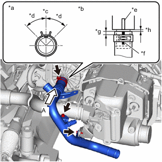
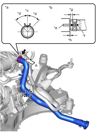
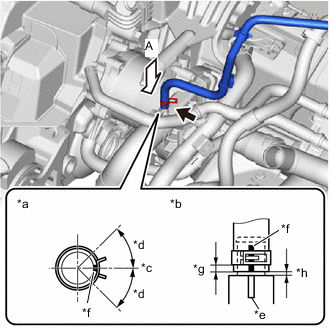
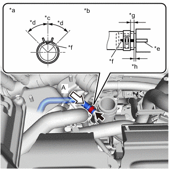
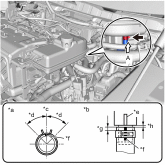
*a View A *b Hose End and Hose Clip Position *c Upper Side of Vehicle *d Area of Claw of Hose Clip: 45° *e Rib of FC Cooling Water Pump Assembly *f Hose Paint Mark (Yellow) *g Distance from Hose End to Hose Clip: 2 to 5 mm (0.0788 to 0.196 in.) *h Distance from Hose End to Stopper Portion: 0 to 2 mm (0 to 0.0787 in.) Install the FC cooling water pump inlet hose to the FC cooling water pump assembly and slide the hose clip to secure it.
Note
Align the hose and hose clip at the locations shown in the illustration and install them.
Tech Tips
When connecting, if the hose is difficult to insert, apply new coolant (Toyota genuine FC stack coolant) to it.
-
Install the FC cooling water pump inlet pipe to the FC cooling water pump inlet bracket and No. 1 FC air compressor outlet pipe with the 2 bolts.
- Torque:
- 8.0 N*m { 82 kgf*cm, 71 in.*lbf }
-
-
INSTALL FC CONVERTER COOLING WATER OUTLET HOSE
-
To prevent contamination by foreign matter or water droplets, remove the plastic bags from the connecting portions of the FC converter cooling water outlet hose and FC air compressor with motor assembly immediately before performing the procedure.
-
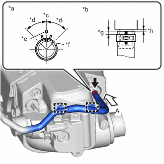
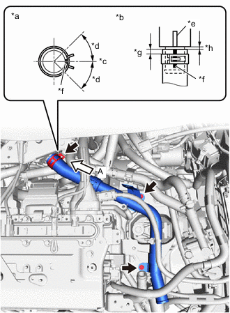
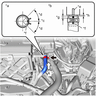
*a View A *b Hose End and Hose Clip Position *c Upper Side of Vehicle *d Area of Claw of Hose Clip: 45° *e Pipe Paint Mark (Yellow) *f Hose Paint Mark (Yellow) *g Distance from Hose End to Hose Clip: 2 to 5 mm (0.0788 to 0.196 in.) Install the FC converter cooling water outlet hose to the FC air compressor with motor assembly and slide the hose clip to secure it.
Note
Align the hose and hose clip at the locations shown in the illustration and install them.
-
Engage the clamp to install the FC converter cooling water outlet hose to the No. 3 FC air compressor outlet pipe bracket.
-
-
INSTALL NO. 2 EV RADIATOR INLET HOSE
-
To prevent contamination by foreign matter or water droplets, remove the plastic bags from the connecting portions of the No. 2 EV radiator inlet hose and FC air compressor with motor assembly immediately before performing the procedure.
-
*a View A *b Hose End and Hose Clip Position *c Upper Side of Vehicle *d Area of Claw of Hose Clip: 45° *e Pipe Paint Mark (White) *f Hose Paint Mark (White) *g Distance from Hose End to Hose Clip: 2 to 5 mm (0.0788 to 0.196 in.) Install the No. 2 EV radiator inlet hose to the FC air compressor with motor assembly and slide the hose clip to secure it.
Note
Align the hose and hose clip at the locations shown in the illustration and install them.
-
-
INSTALL NO. 1 FC COOLING WATER PUMP OUTLET HOSE
-
To prevent contamination by foreign matter or water droplets, remove the plastic bags from the connecting portions of the No. 1 FC cooling water pump outlet hose and FC cooling water pump assembly immediately before performing the procedure.
-
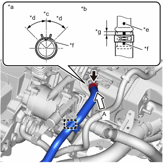
*a View A *b Hose End and Hose Clip Position *c Upper Side of Vehicle *d Area of Claw of Hose Clip: 45° *e Rib of FC Cooling Water Pump Assembly *f Hose Paint Mark (White) *g Distance from Hose End to Hose Clip: 2 to 5 mm (0.0788 to 0.196 in.) *h Distance from Hose End to Stopper Portion: 0 to 2 mm (0 to 0.0787 in.) Install the No. 1 FC cooling water pump outlet hose to the FC cooling water pump assembly and slide the hose clip to secure it.
Note
Align the hose and hose clip at the locations shown in the illustration and install them.
Tech Tips
When connecting, if the hose is difficult to insert, apply new coolant (Toyota genuine FC stack coolant) to it.
-
Engage the clamp to install the No. 2 FC cooling water pump outlet hose to the FC stack cooling water outlet bracket.
-
-
INSTALL INTERCOOLER COOLING WATER INLET HOSE
-
To prevent contamination by foreign matter or water droplets, remove the plastic bags from the connecting portions of the intercooler cooling water inlet hose and FC air compressor with motor assembly immediately before performing the procedure.
-
*a View A *b Hose End and Hose Clip Position *c Upper Side of Vehicle *d Area of Claw of Hose Clip: 45° *e Alignment Mark of FC Air Compressor with Motor Assembly *f Hose Paint Mark (Yellow) *g Distance from Hose End to Hose Clip: 2 to 5 mm (0.0788 to 0.196 in.) *h Distance from Hose End to Stopper Portion: 0 to 2 mm (0 to 0.0787 in.) Install the intercooler cooling water inlet hose to the FC air compressor with motor assembly and slide the hose clip to secure it.
Note
Align the hose and hose clip at the locations shown in the illustration and install them.
Tech Tips
When connecting, if the hose is difficult to insert, apply new coolant (Toyota genuine FC stack coolant) to it.
-
Engage the 2 clamps to install the intercooler cooling water inlet hose to the FC air compressor with motor assembly.
-
To prevent contamination by foreign matter or water droplets, remove the plastic bags from the connecting portions of the intercooler cooling water inlet hose and No. 1 FC cooling water pump outlet hose immediately before performing the procedure.
-
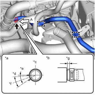
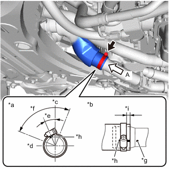
*a View A *b Hose End and Hose Clip Position *c Upper Side of Vehicle *d Right Side of Vehicle *e 19.3° *f Area of Claw Center of Hose Clip: 30° *g Distance from Hose End to Hose Clip: 2 to 7 mm (0.0788 to 0.275 in.) Connect the intercooler cooling water inlet hose to the FC cooling water pump outlet pipe and slide the hose clip to secure it.
Note
Align the hose and hose clip at the locations shown in the illustration and install them.
Tech Tips
When connecting, if the hose is difficult to insert, apply new coolant (Toyota genuine FC stack coolant) to it.
-
Engage the 2 clamps to install the intercooler cooling water inlet hose to the No. 3 FC air compressor outlet pipe bracket and FC cooling water pump inlet pipe.
-
-
INSTALL INTERCOOLER COOLING WATER OUTLET HOSE
-
To prevent contamination by foreign matter or water droplets, remove the plastic bags from the connecting portions of the intercooler cooling water outlet hose and FC air compressor with motor assembly immediately before performing the procedure.
-
*a View A *b Hose End and Hose Clip Position *c Upper Side of Vehicle *d Area of Claw of Hose Clip: 45° *e Alignment Mark of FC Air Compressor with Motor Assembly *f Hose Paint Mark (White) *g Distance from Hose End to Hose Clip: 2 to 5 mm (0.0788 to 0.196 in.) *h Distance from Hose End to Stopper Portion: 0 to 2 mm (0 to 0.0787 in.) Install the intercooler cooling water outlet hose to the FC air compressor with motor assembly and slide the hose clip to secure it.
Note
Align the hose and hose clip at the locations shown in the illustration and install them.
Tech Tips
When connecting, if the hose is difficult to insert, apply new coolant (Toyota genuine FC stack coolant) to it.
-
Engage the 2 clamps to install the intercooler cooling water outlet hose to the No. 3 FC air compressor outlet pipe bracket and FC cooling water pump inlet pipe.
-
-
INSTALL FC WATER PUMP DRAIN HOSE ASSEMBLY
-
To prevent contamination by foreign matter or water droplets, remove the plastic bags from the connecting portions of the FC water pump drain hose assembly and FC cooling water pump assembly immediately before performing the procedure.
-
*a View A *b Hose End and Hose Clip Position *c Right Side of Vehicle *d Area of Claw of Hose Clip: 45° *e Rib of FC Cooling Water Pump Assembly *f Hose Paint Mark (White) *g Distance from Hose End to Hose Clip: 2 to 5 mm (0.0788 to 0.196 in.) *h Distance from Hose End to Stopper Portion: 0 to 2 mm (0 to 0.0787 in.) Install the FC water pump drain hose assembly to the FC cooling water pump assembly and slide the hose clip to secure it.
Note
Align the hose and hose clip at the locations shown in the illustration and install them.
Tech Tips
When connecting, if the hose is difficult to insert, apply new coolant (Toyota genuine FC stack coolant) to it.
-
-
INSTALL FCV TRACTION MOTOR BOND CABLE ASSEMBLY
-
Install the FCV traction motor bond cable assembly to the FC air compressor bracket and FCV transaxle with motor assembly with the 2 bolts.
- Torque:
- 10.5 N*m { 107 kgf*cm, 8 ft.*lbf }
-
-
INSTALL WIRE HARNESS CLAMP BRACKET
-
Install the wire harness clamp bracket to the FC air compressor bracket with the bolt.
- Torque:
- 17.5 N*m { 178 kgf*cm, 13 ft.*lbf }
-
Engage the clamp to install the FC air compressor revolution sensor wire to the wire harness clamp bracket.
-
-
CONNECT MOTOR WIRE
-
Engage the 5 clamps to install the motor wire to the FC air compressor with motor assembly.
-
Connect the 4 connectors.
-
-
INSTALL FCV TRANSAXLE WITH MOTOR ASSEMBLY
-
Operate the engine lifter to slowly lift up the FC air compressor with motor assembly, FCV transaxle with motor assembly and front suspension crossmember sub-assembly to a position where the motor mounting bracket LH can be installed to the motor mounting insulator LH.
Note
Be cautious of wire harnesses, hoses, and the steering intermediate shaft when lifting.
-
Temporarily install the front suspension member rear brace LH, front suspension member rear brace RH and front suspension crossmember sub-assembly to the vehicle body with the 6 bolts.
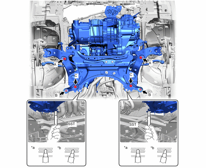
*a OK *b NG -
While alternatingly inserting the SST into the LH side and RH side alignment holes of the front suspension crossmember sub-assembly, fully tighten the 2 bolts (A).
- SST
- 09670-00020
- Torque:
- 137 N*m { 1397 kgf*cm, 101 ft.*lbf }
-
Fully tighten the 2 bolts (B).
- Torque:
- 93 N*m { 948 kgf*cm, 69 ft.*lbf }
-
Fully tighten the 2 bolts (C).
- Torque:
- 137 N*m { 1397 kgf*cm, 101 ft.*lbf }
-
Install the motor mounting bracket LH to the motor mounting insulator LH with the nut.
- Torque:
- 72 N*m { 734 kgf*cm, 53 ft.*lbf }
-
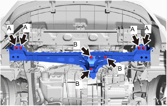
Temporarily install the front crossmember sub-assembly to the front motor mounting insulator and vehicle body with the 7 bolts.
-
Fully tighten the 4 bolts (A).
- Torque:
- 99 N*m { 1010 kgf*cm, 73 ft.*lbf }
-
Lower the engine lifter.
-
Fully tighten the 3 bolts (B).
- Torque:
- 72 N*m { 734 kgf*cm, 53 ft.*lbf }
-
-
INSTALL COMPRESSOR WITH MOTOR ASSEMBLY
CAUTION:
Wear insulated gloves.
-
Using an E8 "TORX" socket wrench, temporarily install the compressor with motor assembly to the FC air compressor with motor assembly with the 2 stud bolts.
- Torque:
- 10 N*m { 102 kgf*cm, 7 ft.*lbf }
-
Install the compressor with motor assembly to the FC air compressor with motor assembly with the bolt and 2 nuts.
- Torque:
- 25 N*m { 255 kgf*cm, 18 ft.*lbf }
-
Engage the clamp to install the compressor cable to the wire harness clamp bracket.
-
Connect the connector.
-
-
CONNECT NO. 1 MOTOR COOLING HOSE
-
CONNECT NO. 3 MOTOR COOLING HOSE
-
CONNECT NO. 2 FC RADIATOR OUTLET HOSE
-
To prevent contamination by foreign matter or water droplets, remove the plastic bags from the connecting portions of the No. 2 FC radiator outlet hose and FC cooling water pump inlet pipe immediately before performing the procedure.
-
*a View A *b Hose End and Hose Clip Position *c Right Side of Vehicle *d Area of Claw of Hose Clip: 45° *e Pipe Paint Mark (Yellow) *f Hose Paint Mark (Yellow) *g Distance from Hose End to Hose Clip: 2 to 5 mm (0.0788 to 0.196 in.) Connect the No. 2 FC radiator outlet hose to the FC cooling water pump inlet pipe and slide the hose clip to secure it.
Note
Align the hose and hose clip at the locations shown in the illustration and install them.
Tech Tips
When connecting, if the hose is difficult to insert, apply new coolant (Toyota genuine FC stack coolant) to it.
-
-
CONNECT NO. 2 FC COOLING BY-PASS HOSE
-
To prevent contamination by foreign matter or water droplets, remove the plastic bags from the connecting portions of the No. 2 FC cooling by-pass hose and FC cooling water pump inlet pipe immediately before performing the procedure.
-
*a View A *b Hose End and Hose Clip Position *c Right Side of Vehicle *d Area of Claw of Hose Clip: 45° *e Pipe Paint Mark (Yellow) *f Hose Paint Mark (Yellow) *g Distance from Hose End to Hose Clip: 2 to 5 mm (0.0788 to 0.196 in.) *h Distance from Hose End to Pipe Connecting Portion: 0 to 2 mm (0 to 0.0787 in.) Connect the No. 2 FC cooling by-pass hose to the FC cooling water pump inlet pipe and slide the hose clip to secure it.
Note
Align the hose and hose clip at the locations shown in the illustration and install them.
Tech Tips
When connecting, if the hose is difficult to insert, apply new coolant (Toyota genuine FC stack coolant) to it.
-
-
CONNECT NO. 2 FC AIR COMPRESSOR OUTLET HOSE
-
To prevent contamination by foreign matter or water droplets, remove the plastic bags from the connecting portions of the No. 2 FC air compressor outlet hose and No. 2 FC air compressor outlet pipe immediately before performing the procedure.
-
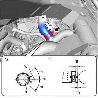
*a View A *b Hose End and Hose Clamp Position *c Upper Side of Vehicle *d Right Side of Vehicle *e 24° *f Area of Threaded Portion of Hose Clamp: 90° *g Pipe Paint Mark (Yellow) *h Hose Paint Mark (Yellow) *i Distance from Hose End to Hose Clamp: 2 to 7 mm (0.0788 to 0.275 in.) Connect the No. 2 FC air compressor outlet hose to the No. 2 FC air compressor outlet pipe and tighten the hose clamp to secure it.
- Torque:
- 6.3 N*m { 64 kgf*cm, 56 in.*lbf }
Note
-
Before installing, check that no foreign matter has entered from the connecting portions.
-
Align the hose and hose clamp at the locations shown in the illustration and install them.
-
-
INSTALL FC CONVERTER COOLING WATER OUTLET HOSE
-
Engage the clamp to install the FC converter cooling water outlet hose to the vehicle body.
-
-
CONNECT NO. 2 EV WATER HOSE CONNECTOR
-
INSTALL NO. 2 FC COOLING WATER VALVE INLET HOSE
-
Engage the clamp to install the No. 2 FC cooling water valve inlet hose to the rear motor mounting insulator.
-
-
INSTALL NO. 2 INVERTER COOLING OUTLET HOSE
-
Engage the clamp to install the No. 2 inverter cooling outlet hose to the rear motor mounting insulator.
-
-
INSTALL HYDROGEN PUMP INVERTER CABLE
CAUTION:
Wear insulated gloves.
-
Engage the 2 clamps to install the hydrogen pump inverter cable to the rear motor mounting insulator.
-
-
INSTALL FC CONVERTER POWER OUTLET CABLE
CAUTION:
Wear insulated gloves.
-
Engage the clamp to install the FC converter power outlet cable to the rear motor mounting insulator.
-
-
INSTALL REAR SIDE RAIL REINFORCEMENT SUB-ASSEMBLY LH
-
INSTALL REAR SIDE RAIL REINFORCEMENT SUB-ASSEMBLY RH
-
INSTALL FRONT DRIVE SHAFT ASSEMBLY
-
PLACE FRONT WHEELS FACING STRAIGHT AHEAD
-
INSTALL NO. 1 STEERING COLUMN HOLE COVER SUB-ASSEMBLY
-
CONNECT NO. 2 STEERING INTERMEDIATE SHAFT ASSEMBLY
-
INSTALL COLUMN HOLE COVER SILENCER SHEET
-
CONNECT FCV TRACTION MOTOR BOND CABLE ASSEMBLY
-
Connect the FCV traction motor bond cable assembly to the center frame crossmember sub-assembly with the bolt.
- Torque:
- 10.5 N*m { 107 kgf*cm, 8 ft.*lbf }
-
-
CONNECT MOTOR WIRE
-
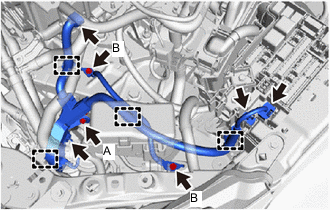
Engage the 4 clamps to install the motor wire.
-
Install the motor wire with the 3 bolts.
- Torque:
- Bolt A
- 7.0 N*m { 71 kgf*cm, 62 in.*lbf }
- Bolt B
- 8.4 N*m { 86 kgf*cm, 74 in.*lbf }
Bolt Length (not including head) Item Length Bolt A 20 mm (0.787 in.) Bolt B 15 mm (0.591 in.) -
Connect the 4 connectors.
-
-
INSTALL NO. 1 RELAY BLOCK COVER
-
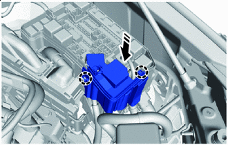

Install in this Direction Install the No. 1 relay block cover to the motor compartment relay block and engage the 2 claws.
-
-
INSTALL UPPER NO. 1 RELAY BLOCK COVER
-
CONNECT FC COOLING WATER PUMP CABLE
CAUTION:
Wear insulated gloves.
-
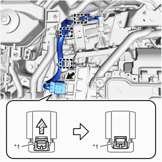
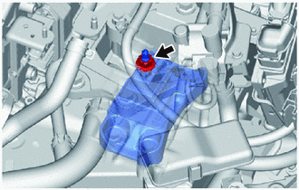
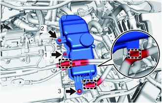
*1 Green-colored Lock Engage the 3 clamps to install the FC cooling water pump cable.
-
As shown in the illustration, connect the FC cooling water pump cable connector and press in the green-colored lock to securely fix the connector in place.
Note
-
Do not touch the connector terminals.
-
Check that the connector is securely connected.
-
-
-
REMOVE INVERTER TERMINAL COVER
-
CONNECT FC AIR COMPRESSOR CABLE
CAUTION:
Wear insulated gloves.
Note
Do not allow foreign matter or water droplets to enter the inverter with converter assembly.
-
Engage the clamp to install the FC air compressor cable to the motor cable bracket.
-
To prevent contamination by foreign matter or water droplets, remove the protective tape from the openings of the inverter with converter assembly immediately before performing the procedure.
-
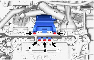
Temporarily install the FC air compressor cable to the inverter with converter assembly with the 5 bolts.
Note
-
To prevent damage to the threaded portion, be sure to perform the procedures by hand.
-
Do not touch the connector rubber seal or terminals.
-
Do not damage the terminals, connector housings or inverter with converter assembly during connection.
-
-
Using an insulated tool, fully tighten the 2 bolts (A).
- Torque:
- 8.0 N*m { 82 kgf*cm, 71 in.*lbf }
-
Using an insulated tool, fully tighten the 3 bolts (B).
- Torque:
- 8.0 N*m { 82 kgf*cm, 71 in.*lbf }
-
-
CONNECT MOTOR CABLE
CAUTION:
Wear insulated gloves.
Note
Do not allow foreign matter or water droplets to enter the inverter with converter assembly.
-
Engage the clamp to install the motor cable to the motor cable bracket.
-
To prevent contamination by foreign matter or water droplets, remove the protective tape from the openings of the inverter with converter assembly immediately before performing the procedure.
-
Temporarily install the motor cable to the inverter with converter assembly with the 5 bolts.
Note
-
To prevent damage to the threaded portion, be sure to perform the procedures by hand.
-
Do not touch the connector rubber seal or terminals.
-
Do not damage the terminals, connector housings or inverter with converter assembly during connection.
-
-
Using an insulated tool, fully tighten the 2 bolts (A).
- Torque:
- 8.0 N*m { 82 kgf*cm, 71 in.*lbf }
-
Using an insulated tool, fully tighten the 3 bolts (B).
- Torque:
- 8.0 N*m { 82 kgf*cm, 71 in.*lbf }
-
-
INSTALL FC INVERTER INPUT JUNCTION ASSEMBLY
-
INSTALL INVERTER TERMINAL COVER
-
CONNECT FRAME WIRE
-
INSTALL FC INVERTER INPUT JUNCTION COVER
-
CONNECT FC WATER PUMP DRAIN HOSE ASSEMBLY
-
Engage the 3 clamps to install the FC water pump drain hose assembly to the No. 2 FC cooling water pump cable bracket.
-
Install the FC water pump drain hose assembly to the FC inverter input junction assembly with the bolt.
- Torque:
- 13 N*m { 133 kgf*cm, 10 ft.*lbf }
-
-
CONNECT NO. 2 EV RADIATOR INLET HOSE
-
To prevent contamination by foreign matter or water droplets, remove the plastic bags from the connecting portions of the No. 2 EV radiator inlet hose and EV radiator inlet pipe immediately before performing the procedure.
-
*a View A *b Hose End and Hose Clip Position *c Upper Side of Vehicle *d Area of Claw of Hose Clip: 45° *e Pipe Paint Mark (Yellow) *f Hose Paint Mark (Yellow) *g Distance from Hose End to Hose Clip: 2 to 5 mm (0.0788 to 0.196 in.) Connect the No. 2 EV radiator inlet hose to the EV radiator inlet pipe and slide the hose clip to secure it.
Note
Align the hose and hose clip at the locations shown in the illustration and install them.
-
Engage the clamp to install the No. 2 EV radiator inlet hose to the EV water pump outlet pipe.
-
-
CONNECT INTERCOOLER COOLING WATER OUTLET HOSE
-
To prevent contamination by foreign matter or water droplets, remove the plastic bags from the connecting portions of the intercooler cooling water outlet hose and FC cooling water valve inlet pipe immediately before performing the procedure.
-
*a View A *b Hose End and Hose Clip Position *c Upper Side of Vehicle *d Area of Claw of Hose Clip: 45° *e Rib of FC Cooling Water Valve Inlet Pipe *f Hose Paint Mark (Yellow) *g Distance from Hose End to Hose Clip: 2 to 5 mm (0.0788 to 0.196 in.) *h Distance from Hose End to Stopper Portion: 0 to 2 mm (0 to 0.0787 in.) Connect the intercooler cooling water outlet hose to the FC cooling water valve inlet pipe and slide the hose clip to secure it.
Note
Align the hose and hose clip at the locations shown in the illustration and install them.
Tech Tips
When connecting, if the hose is difficult to insert, apply new coolant (Toyota genuine FC stack coolant) to it.
-
-
INSTALL FC COOLING WATER TEMPERATURE CONTROL VALVE
-
INSTALL FC RADIATOR INLET PIPE
-
To prevent contamination by foreign matter or water droplets, remove the plastic bags from the connecting portions of the No. 1 FC cooling water valve outlet hose and FC cooling water temperature control valve immediately before performing the procedure.
-
*a View A *b Hose End and Hose Clip Position *c Rear Side of Vehicle *d Area of Claw of Hose Clip: 45° *e Rib of FC Cooling Water Temperature Control Valve *f Hose Paint Mark (White) *g Distance from Hose End to Hose Clip: 2 to 5 mm (0.0788 to 0.196 in.) *h Distance from Hose End to Stopper Portion: 0 to 2 mm (0 to 0.0787 in.) Connect the No. 1 FC cooling water valve outlet hose to the FC cooling water temperature control valve and slide the hose clip to secure it.
Note
Align the hose and hose clip at the locations shown in the illustration and install them.
Tech Tips
When connecting, if the hose is difficult to insert, apply new coolant (Toyota genuine FC stack coolant) to it.
-
Install the FC radiator inlet pipe to the center frame crossmember sub-assembly with the 2 bolts.
- Torque:
- 8.0 N*m { 82 kgf*cm, 71 in.*lbf }
-
-
CONNECT FC RADIATOR INLET HOSE
-
To prevent contamination by foreign matter or water droplets, remove the plastic bags from the connecting portions of the FC radiator inlet hose and FC radiator inlet pipe immediately before performing the procedure.
-
*a View A *b Hose End and Hose Clip Position *c Upper Side of Vehicle *d Area of Claw of Hose Clip: 45° *e Pipe Paint Mark (White) *f Hose Paint Mark (White) *g Distance from Hose End to Hose Clip: 2 to 5 mm (0.0788 to 0.196 in.) Connect the FC radiator inlet hose to the FC radiator inlet pipe and slide the hose clip to secure it.
Note
Align the hose and hose clip at the locations shown in the illustration and install them.
Tech Tips
When connecting, if the hose is difficult to insert, apply new coolant (Toyota genuine FC stack coolant) to it.
-
-
INSTALL NO. 2 WATER HOSE SUB-ASSEMBLY
-
Engage the clamp to install the No. 2 water hose sub-assembly to the No. 1 FC cooling water valve outlet hose.
-
-
INSTALL HEATER WATER INLET B HOSE
-
Engage the clamp to install the heater water inlet B hose to the FC radiator inlet pipe.
-
-
INSTALL INVERTER RESERVE TANK ASSEMBLY
-
To prevent contamination by foreign matter or water droplets, remove the plastic bags from the connecting portions of the No. 1 inverter drain hose and inverter reserve tank assembly immediately before performing the procedure.
-
*a View A *b Hose End and Hose Clip Position *c Rear Side of Vehicle *d Area of Claw of Hose Clip: 45° *e Rib of Inverter Reserve Tank Assembly *f Hose Paint Mark (Yellow) *g Distance from Hose End to Hose Clip: 2 to 5 mm (0.0788 to 0.196 in.) *h Distance from Hose End to Stopper Portion: 0 to 2 mm (0 to 0.0787 in.) Connect the No. 1 inverter drain hose to the inverter reserve tank assembly and slide the hose clip to secure it.
Note
Align the hose and hose clip at the locations shown in the illustration and install them.
-
Temporarily install the inverter reserve tank assembly to the inverter with converter assembly and inverter protector with the 2 bolts and nut.
-
Fully tighten the 2 bolts and nut in the order shown in the illustration.
- Torque:
- Bolt
- 6.5 N*m { 66 kgf*cm, 58 in.*lbf }
- Nut
- 6.0 N*m { 61 kgf*cm, 53 in.*lbf }
-
Engage the 3 clamps to install the wire harness to the inverter reserve tank assembly.
-
-
CONNECT NO. 2 INVERTER COOLING HOSE
-
To prevent contamination by foreign matter or water droplets, remove the plastic bags from the connecting portions of the No. 2 inverter cooling hose and inverter reserve tank assembly immediately before performing the procedure.
-
*a View A *b Hose End and Hose Clip Position *c Left Side of Vehicle *d Area of Claw of Hose Clip: 45° *e Rib of Inverter Reserve Tank Assembly *f Hose Paint Mark (White) *g Distance from Hose End to Hose Clip: 2 to 5 mm (0.0788 to 0.196 in.) *h Distance from Hose End to Stopper Portion: 0 to 2 mm (0 to 0.0787 in.) Connect the No. 2 inverter cooling hose to the inverter reserve tank assembly and slide the hose clip to secure it.
Note
Align the hose and hose clip at the locations shown in the illustration and install them.
-
-
CONNECT NO. 2 INVERTER DRAIN HOSE
-
To prevent contamination by foreign matter or water droplets, remove the plastic bags from the connecting portions of the No. 2 inverter drain hose and inverter reserve tank assembly immediately before performing the procedure.
-
*a View A *b Hose End and Hose Clip Position *c Upper Side of Vehicle *d Area of Claw of Hose Clip: 45° *e Rib of Inverter Reserve Tank Assembly *f Hose Paint Mark (Yellow) *g Distance from Hose End to Hose Clip: 2 to 5 mm (0.0788 to 0.196 in.) *h Distance from Hose End to Stopper Portion: 0 to 2 mm (0 to 0.0787 in.) Connect the No. 2 inverter drain hose to the inverter reserve tank assembly and slide the hose clip to secure it.
Note
Align the hose and hose clip at the locations shown in the illustration and install them.
-
-
INSTALL INVERTER COVER
-
Install in this Direction Engage the 4 grommets to install the inverter cover to the inverter with converter assembly and inverter protector.
Note
Press the upper surface of the inverter cover grommet portion to securely engage the grommet.
-
-
INSTALL AIR CLEANER HOSE ASSEMBLY
-
To prevent contamination by foreign matter or water droplets, remove the plastic bags from the connecting portions of the air cleaner hose assembly and FC air compressor with motor assembly immediately before performing the procedure.
-
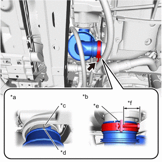
*a Top View *b Bottom View *c Groove of FC Air Compressor with Motor Assembly *d Cutout of Air Cleaner Hose Assembly *e Detent of Hose Clamp *f Hose Clamp Bolt Protrusion Amount: 7 mm (0.275 in.) or less Connect the air cleaner hose assembly to the FC air compressor with motor assembly and tighten the hose clamp to secure it.
Note
-
Before installing, check that no foreign matter has entered from the connecting portions.
-
Align the hose and hose clamp at the locations shown in the illustration and install them.
-
-
-
INSTALL AIR CLEANER WITH ELEMENT ASSEMBLY
-
Engage the pin to temporarily install the air cleaner with element assembly to the FC inverter input junction assembly.
-
Install the air cleaner with element assembly to the hood lock support sub-assembly and inverter protector with the 2 bolts.
- Torque:
- 5.0 N*m { 51 kgf*cm, 44 in.*lbf }
-
Engage the clamp to install the wire harness to the air cleaner with element assembly.
-
Connect the connector of the intake mass air flow meter sub-assembly.
-
To prevent contamination by foreign matter or water droplets, remove the plastic bags from the connecting portions of the air cleaner hose assembly and air cleaner with element assembly immediately before performing the procedure.
-
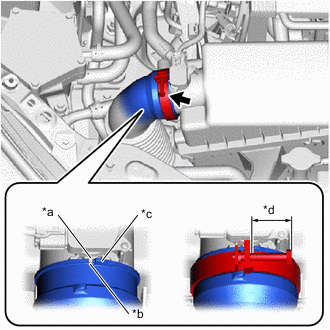
*a Protrusion of Air Cleaner with Element Assembly *b Cutout of Air Cleaner Hose Assembly *c Detent of Hose Clamp *d Hose Clamp Bolt Protrusion Amount: 10 mm (0.393 in.) or less Connect the air cleaner hose assembly to the air cleaner with element assembly and tighten the hose clamp to secure it.
Note
-
Before installing, check that no foreign matter has entered from the connecting portions.
-
Align the hose and hose clamp at the locations shown in the illustration and install them.
-
-
-
INSTALL AIR CLEANER INLET
-
Connect the air cleaner inlet to the air cleaner with element assembly.
-
Install the air cleaner inlet to the hood lock support sub-assembly with the bolt and clip.
- Torque:
- 5.0 N*m { 51 kgf*cm, 44 in.*lbf }
-
-
INSTALL COOL AIR INTAKE DUCT SEAL
-
INSTALL OUTER COWL TOP PANEL SUB-ASSEMBLY (for LHD)
-
INSTALL OUTER COWL TOP PANEL SUB-ASSEMBLY (for RHD)
-
INSTALL COWL BODY MOUNTING REINFORCEMENT RH (for LHD)
-
INSTALL COWL BODY MOUNTING REINFORCEMENT RH (for RHD)
-
INSTALL WATER GUARD PLATE LH (for LHD)
-
INSTALL WATER GUARD PLATE RH (for RHD)
-
INSTALL NO. 2 HEATER AIR DUCT SPLASH SHIELD SEAL (for LHD)
-
INSTALL NO. 1 HEATER AIR DUCT SPLASH SHIELD SEAL (for RHD)
-
INSTALL WINDSHIELD WIPER MOTOR AND LINK
-
INSTALL FC STACK SERVICE PLUG GRIP
-
INSTALL SERVICE PLUG GRIP (for EV)
-
ADD HYBRID TRANSAXLE FLUID
-
ADD COOLANT (for Inverter)
-
ADD COOLANT (FC STACK COOLANT)
-
INSPECT AND ADJUST HYBRID TRANSAXLE FLUID
-
INSPECT FOR HYBRID TRANSAXLE FLUID LEAK
-
INSPECT FOR COOLANT LEAK (for Inverter)
-
INSPECT FOR COOLANT (FC STACK COOLANT) LEAK
-
INSTALL SUSPENSION MEMBER TO FRONT CROSSMEMBER BRACE SUB-ASSEMBLY
-
INSTALL FRONT FLOOR COVER RH
-
INSTALL FRONT FLOOR COVER LH
-
INSTALL REAR MOTOR UNDER COVER LH
-
INSTALL REAR MOTOR UNDER COVER RH
-
INSTALL NO. 2 MOTOR UNDER COVER
-
INSTALL NO. 1 MOTOR UNDER COVER
-
INSTALL NO. 3 RADIATOR AIR GUIDE
-
INSTALL FRONT BUMPER LOWER ABSORBER
-
INSPECT AND ADJUST FRONT WHEEL ALIGNMENT