AIR COMPRESSOR REASSEMBLY

PROCEDURE
-
INSTALL FC AIR COMPRESSOR LOWER COVER
-
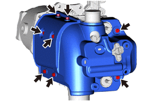
Install the FC air compressor lower cover to the FC air compressor with motor assembly with the 8 bolts.
- Torque:
- 11.8 N*m { 120 kgf*cm, 9 ft.*lbf }
-
-
INSTALL FC AIR COMPRESSOR UPPER COVER
-
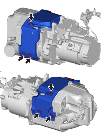
Install the FC air compressor upper cover to the FC air compressor with motor assembly with the 6 bolts.
- Torque:
- 11.8 N*m { 120 kgf*cm, 9 ft.*lbf }
-
-
INSTALL FC AIR COMPRESSOR MOTOR COOLING INLET HOSE
-
To prevent contamination by foreign matter or water droplets, remove the plastic bags from the connecting portions of the FC air compressor motor cooling inlet hose and FC air compressor motor cooling inlet pipe immediately before performing the procedure.
-
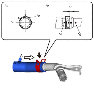
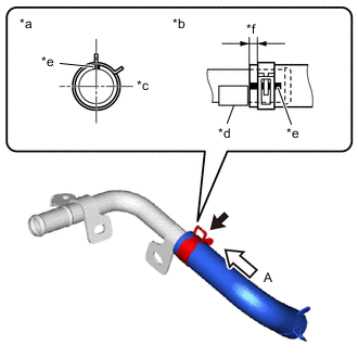
*a View A *b Hose End and Hose Clip Position *c FC Air Compressor with Motor Assembly Side *d Pipe Paint Mark (Blue) *e Hose Paint Mark (Blue) *f Distance from Hose End to Hose Clip: 2 to 5 mm (0.0788 to 0.196 in.) Install the FC air compressor motor cooling inlet hose to the FC air compressor motor cooling inlet pipe, and slide the hose clip to secure it.
Note
Align the hose and hose clip at the locations shown in the illustration and install them.
-
-
INSTALL FC AIR COMPRESSOR MOTOR COOLING INLET PIPE
-
To prevent contamination by foreign matter or water droplets, remove the plastic bags from the connecting portions of the FC air compressor motor cooling inlet hose and FC air compressor with motor assembly immediately before performing the procedure.
-
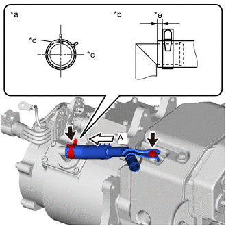
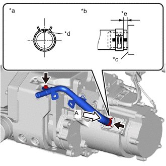
*a View A *b Hose End and Hose Clip Position *c FC Air Compressor with Motor Assembly Side *d Hose Paint Mark (Blue) *e Distance from Hose End to Hose Clip: 2 to 5 mm (0.0788 to 0.196 in.) Connect the FC air compressor motor cooling inlet hose, and install the FC air compressor motor cooling inlet pipe to the FC air compressor with motor assembly with the bolt.
- Torque:
- 8.0 N*m { 82 kgf*cm, 71 in.*lbf }
-
Slide the hose clip to secure the FC air compressor motor cooling inlet hose.
Note
Align the hose and hose clip at the locations shown in the illustration and install them.
-
-
INSTALL FC AIR COMPRESSOR MOTOR COOLING OUTLET HOSE
-
To prevent contamination by foreign matter or water droplets, remove the plastic bags from the connecting portions of the FC air compressor motor cooling outlet hose and FC air compressor motor cooling outlet pipe immediately before performing the procedure.
-
*a View A *b Hose End and Hose Clip Position *c FC Air Compressor with Motor Assembly Side *d Bracket Portion *e Hose Paint Mark (Blue) *f Distance from Hose End to Hose Clip: 2 to 5 mm (0.0788 to 0.196 in.) Install the FC air compressor motor cooling outlet hose to the FC air compressor motor cooling outlet pipe, and slide the hose clip to secure it.
Note
Align the hose and hose clip at the locations shown in the illustration and install them.
-
-
INSTALL FC AIR COMPRESSOR MOTOR COOLING OUTLET PIPE
-
To prevent contamination by foreign matter or water droplets, remove the plastic bags from the connecting portions of the FC air compressor motor cooling outlet hose and FC air compressor with motor assembly immediately before performing the procedure.
-
*a View A *b Hose End and Hose Clip Position *c Stopper Portion *d Hose Paint Mark (Yellow) *e Distance from Hose End to Hose Clip: 2 to 5 mm (0.0788 to 0.196 in.) Connect the FC air compressor motor cooling outlet hose, and install the FC air compressor motor cooling outlet pipe to the FC air compressor with motor assembly with the bolt.
- Torque:
- 8.0 N*m { 82 kgf*cm, 71 in.*lbf }
-
Slide the hose clip to secure the FC air compressor motor cooling outlet hose.
Note
Align the hose and hose clip at the locations shown in the illustration and install them.
-
-
INSTALL FC AIR COMPRESSOR REVOLUTION SENSOR WIRE
-
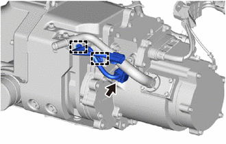
Connect the connector to install the FC air compressor revolution sensor wire to the FC air compressor with motor assembly.
-
Engage the 2 clamps to install the FC air compressor revolution sensor wire to the FC air compressor motor cooling outlet pipe.
-